background image

ADM-880C 07/20/09

36

6.5.1  CHEMICAL EXHAUST HOODS - VELGRID

The VelGrid provides the average of 16 measurement points at 3.5 inch centers, and represents a 14" x 14" area for each
reading.  When using the VelGrid for chemical exhaust hood readings, the sash opening must be set at a minimum opening
of 14 inches in width for horizontal sliding sash, or 14 inches in height for vertically adjustable sash.  If the opening is less
than 14 inches in width or length, the AirFoil probe should be used.

The VelGrid must be carefully positioned so that the perimeter orifices of the VelGrid are at least 1.75 inches in from the
edge of the opening.  The leading (side the air strikes first) surface of the VelGrid should be evenly aligned and parallel with
the plane of the sash.  Correct positioning of the VelGrid is easier if equal length, stiff wire "feelers" are taped to the leading
surface of the VelGrid.  Coat hanger wire taped in place with plastic electrical tape works well for this purpose.

6.5.2  LAMINAR FLOW WORKSTATION - VELGRID

The VelGrid can be used to measure average face velocities at the work zone or plane of a laminar work station using much
the same method as described for chemical exhaust hoods.  It is important to position the leading edge of the VelGrid at
90 degrees to the direction of air flow when measuring work zone velocities.  The VelGrid may also be positioned so the
1.5 inch standoffs are placed directly against the perforated supply panel face.  The velocity average obtained in this manner
can be used to calculate the volumetric air flow rate as described in Section 6.5.3 AIR FLOW CALCULATION.

6.5.3  AIR FLOW CALCULATION FROM VELGRID VELOCITY

Accurate volumetric air flow calculation using the average face velocity requires careful measurement of the 

active gross

face area

 of the filter, grille, coil, or opening.  Be sure to deduct the area of all obstructions to air passage through the device

to be tested, such as: support bands; T-bars, including the perimeter glue line; and repaired areas of HEPA filters.

Even with careful measurement of the active area, the meter and the sensing probe will be affected by different design
configurations of the outlet, inlet, filter, coil or exhaust hood.  It is best to establish a procedure and confirm the air flow by
pitot tube duct traverse or some other reliable flow measurement means for a given type of air movement device.
IMPORTANT:  See Section 6.1 VELOCITY CORRECTION FACTORS.

The measurement of exhaust hood intake velocity requires careful placement of the VelGrid to align the leading edge of
the grid directly in line with the plane of the sash opening.  Maintain the 1.5" perimeter margin as illustrated.  The total intake
area and air flow of an exhaust hood includes all areas of air entry, including the space behind and around the sash; under
the threshold; and through service openings.  It is accepted practice to assume that the velocity through these additional
areas is the same as that of the sash opening area.  (See the following section regarding hot wire anemometer reading
correction for true air velocity).

6.6  VELOCITY:  LOCAL DENSITY VERSUS STANDARD DENSITY (MASS FLOW)

The AirData Multimeter measures 

true

 air velocity past the sensor at a given time, when used in the 

local density

 mode.

This is in contrast to thermal anemometers or "hot wire" instruments which measure mass flow (mass flux/unit time).  Mass
flow represents the number of molecules of air flowing past a given point during a given time.  Mass flow only represents
true velocity when measured at standard sea level conditions of 29.921 in Hg and 70

/

 F (.075 lbs/cu ft).  Hot wire, mass flow,

"velocity" readings at density conditions other than standard must be corrected for local air density conditions if these results
are to represent true velocity.

Air velocity readings taken with the ADM-880C in the 

standard density

 mode are comparable to readings taken with a hot

wire anemometer.  If local density corrected velocity readings taken with the AirData Multimeter are to be compared with
hot wire anemometer readings, the actual air velocity should be measured in the 

local density

 mode with the AirData

Multimeter, and the 

hot wire readings must be corrected

 for local air density conditions.

The precise method for calculating density corrected air velocity measurements taken with a 

hot


wire anemometer

 requires

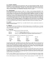
the use of the following equation:

Where:

P

b

 = local barometric pressure (in Hg)

/

 F = temperature of air stream

Содержание AIRDATA ADM-880C

Страница 1: ...ale Arizona 85260 3430 Phone 480 991 6744 Fax 480 443 1267 www shortridge com S i AIRDATA MULTIMETER ADM 880C ELECTRONIC MICROMANOMETER WITH 2000 READING MEMORY DATALOGGING CAPABILITY AND RS232 COMMUN...

Страница 2: ...G 21 5 5 SCAN KEY 21 5 5 1 SCROLL THROUGH MEMORY ASCENDING 21 5 5 2 RESET DISPLAY 21 5 6 READ SELECT KEY 21 5 6 1 MANUAL READINGS 21 5 6 2 AUTOMATIC READINGS 22 5 6 3 TREND READINGS 22 5 6 4 SELECT 22...

Страница 3: ...SSURE PROBES 38 7 1 2 PITOT TUBE VELOCITY PRESSURES 38 7 1 3 PITOT TUBE STATIC PRESSURES 38 7 1 4 PITOT TUBE TOTAL PRESSURES 39 7 2 ABSOLUTE PRESSURE 39 8 0 TEMPERATURE MEASUREMENT 40 8 1 TEMPROBE 40...

Страница 4: ...SON READING 56 14 8 NONBACKPRESSURE COMPENSATED READING 56 15 0 METER MAINTENANCE 57 16 0 FLOWHOOD MAINTENANCE 57 17 0 RECALIBRATION AND REPAIR INFORMATION 58 AIR BALANCE MANUALS TRAINING PROGRAMS 58...

Страница 5: ...UBE 32 6 2 AIRFOIL PROBE 34 6 3 VELGRID ASSEMBLY 37 7 1 STATIC PRESSURE PROBE 38 8 1 ADT442 TEMPROBE 40 8 2 AIRDATA MULTITEMP 41 10 1 FRAME STORAGE 45 10 2 FLOWHOOD IN CASE 45 10 3 FLOWHOOD ASSEMBLY 4...

Страница 6: ...c reading mode which registers repeated measurements in any mode with sequential storage and recall of up to 2000 automatically or individually stored readings with sequence tags for each value Readin...

Страница 7: ...r flow or standard density sea level equivalent mass flow for air flow or velocity Readings are corrected for the density effects of temperature and absolute pressure MEMORY 2000 readings with sequent...

Страница 8: ...The meter is fully operational during recharge OPERATIONAL TEMPERATURE LIMITS The specified accuracy for measurements is maintained over a meter exposure temperature range of 40 F to 140 F 5 C to 60...

Страница 9: ...in memory CLEAR Clear memory CHANGE Change mem group erase replace READ Initiate reading halt read sequence SELECT Select displayed option AUTO Automatic readings TREND TREND readings SCAN Recall in...

Страница 10: ...Local or Standard VelGrid velocity End Time Time AirFoil velocity Number of Readings Date Pitot tube velocity Absolute pressure FlowHood air flow VIEW STATISTICS ASSOCIATED DATA DOWNLOAD Average Mode...

Страница 11: ...the meter in a recess near the upper left corner This switch is used to reset the meter in the unlikely event that the microprocessor becomes lost in its program This may occur if the meter is dropped...

Страница 12: ...PROMPTS The following ten prompts all include the term READ which is a signal for the operator to press the READ key to trigger the actual measurement English Units CF READ This display indicates tha...

Страница 13: ...pensated for backpressure effects Pa nnn nn Indicates that the result represents a differential pressure measurement Pa MS nnn nn Indicates that the displayed result represents a velocity measurement...

Страница 14: ...n This message indicates that nonbackpressure compensated air flow readings have been stored The display shows the reading and its order in the stored reading sequence nn0n nnnn Displays the number of...

Страница 15: ...READ key is pressed when in the absolute pressure measurement mode It is also part of the ASSOCIATED READING sequence and precedes the display of an absolute pressure reading associated with a flow or...

Страница 16: ...he meter is calculating the statistics for a large memory group CHANGE This message indicates that a connection to the meter such as the TemProbe has been altered CHANGE may be preceded by the display...

Страница 17: ...so displayed as part of the sequence of displays when the associated readings are being viewed by pressing ALT VIEW following a pitot tube velocity reading It precedes the display of the velocity pres...

Страница 18: ...adings will be corrected for local air density The meter automatically starts up in the local density mode unless the meter was last turned off with readings stored in the standard density mode LOC DE...

Страница 19: ...n damaged so as to create an open circuit NO READING This is part of the ASSOCIATED READING sequence and is displayed when an associated reading is not available for that type of primary reading NO ST...

Страница 20: ...f the ASSOCIATED reading sequence and precedes the final display of the primary reading selected by the user RECHARGE This message signals that the batteries have reached the end of their useful charg...

Страница 21: ...ement mode A change in the TemProbe setup while storing air flow or velocity readings requires the user to select a new memory group as readings stored with actual and standard temperatures must not b...

Страница 22: ...temperature measurement being attempted exceeds the lower range of the meter UNITS XX This message will be displayed to indicate the units in which readings are being stored It is also one of the par...

Страница 23: ...key is used to select a measurement mode from the options available differential pressure absolute pressure temperature air flow pitot tube velocity AirFoil velocity or VelGrid velocity Scroll throug...

Страница 24: ...number nine requires one key press After a pause the meter moves the cursor to the next prompting position to the right automatically The cursor may also be moved using the SCAN and SCAN keys 5 1 4 GE...

Страница 25: ...display the selected measurement mode for instance VELGRID and the density selected LOCAL or STANDARD If the TemProbe is connected PROBE will be displayed followed by the date and time If the temperat...

Страница 26: ...be erased or replaced in the current or a prior memory group as described in Sections 5 7 3 2 REPLACE READING IN MEMORY or 5 7 3 3 ERASE READING IN MEMORY and the revised statistics and associated da...

Страница 27: ...STORE KEY The STORE key is used to select a STORE mode CLEAR all readings in memory and CHANGE memory The options under CHANGE memory include exiting the current memory group and selecting a new memo...

Страница 28: ...nsity was changed and the meter is being used in the FlowHood or velocity modes the meter will also display DENS CHANGE NOT ALLOWD and will not store a reading until the density is set back to that pr...

Страница 29: ...w statistics will represent the remaining nine readings When the erased reading is viewed using a SCAN key the meter will display the reading sequence number and memory group letter and the word ERASE...

Страница 30: ...display will read NO READING For example the meter will display differential pressure in association with pitot tube measurements but not in association with VelGrid AirFoil or FlowHood readings 5 8 3...

Страница 31: ...is exited the meter will interpret the BEGIN TIME as being on the following day ENTRY DEFAULT DISPLAY PROCEDURE ALTERNATE PROCEDURE Interval Length 00 00 15 I Enter interval between 00 00 15 and 24 00...

Страница 32: ...ecified using the configuration loop These settings are saved indefinitely in memory with the exception of standard density The meter always initializes in the local density mode unless the user has s...

Страница 33: ...configured for autostart the installation software will begin within a few seconds If the installation does not begin open Windows Explorer navigate to the root directory of the CD drive and double cl...

Страница 34: ...d off the user will have approximately 20 minutes of runtime before the meter displays RECHARGE SHUT DOWN and turns itself off The time period will vary depending on prior use The batteries must be re...

Страница 35: ...3 4 Avg 90 7 F 28 6 Hg 0 0099 In Sum 272 1 F 85 8 Hg 0 0394 In Min 89 7 F 28 6 Hg 0 0087 In Max 91 8 F 28 6 Hg 0 0106 In Std Dev 1 05 F 0 Hg 0 00081 In Group B Local 0001B AirFoil 293 FPM 75 6 F 28 6...

Страница 36: ...use Ak factors when calculating the air flow for diffusers with uneven throw and other special applications The use of an Ak factor is not appropriate however in the measurement of face velocities wo...

Страница 37: ...This is not altogether true The measurement of the air velocity in Step 4 is affected by the position and orientation of the air velocity measuring probe By selective experimental positioning of the...

Страница 38: ...and average and will be recalled as nns NP 0 A memory sequence cannot be started with a NEG PITOT reading Air flow within a duct may be calculated by multiplying the average duct air velocity fpm as m...

Страница 39: ...f the AirFoil probe The individual readings for the downflow grid should be recorded to establish the uniformity or zone velocity profile and compliance with the standards required Also the average of...

Страница 40: ...alculate the approximate average velocity for the duct 6 5 VELGRID AIR VELOCITY IMPORTANT See Section 6 1 VELOCITY CORRECTION FACTORS The VelGrid accessory is designed especially for use in the measur...

Страница 41: ...d by different design configurations of the outlet inlet filter coil or exhaust hood It is best to establish a procedure and confirm the air flow by pitot tube duct traverse or some other reliable flo...

Страница 42: ...ADM 880C 07 20 09 37 FIGURE 6 3 VELGRID ASSEMBLY...

Страница 43: ...f the meter Leave the negative port open to the room air Insert the static pressure probe into a 3 8 hole drilled into the duct until the magnet is flush with the surface of the duct Point the tip of...

Страница 44: ...ABS PRES is displayed The meter will then display Hg READ or Bar READ Press the READ key to take a reading CAUTION If an absolute pressure source is likely to be greater than 60 in Hg 30 psia the pres...

Страница 45: ...sion wand to temperatures above 200 F NOTICE The use of more than one temperature cable extender may reduce the meter reading by a non linear degree depending on the combination of cable type length a...

Страница 46: ...primary MultiTemp using plug adapter P N PA 447 Each switch position of the primary MultiTemp can support up to eight switch positions on a secondary MultiTemp The temperature probes used with the Mul...

Страница 47: ...ets These outlets cause an extreme concentration of air velocity on portions of the flow sensing grid The FlowHood readings may be inaccurate under such conditions Consideration must be given to other...

Страница 48: ...humbnut and splice angle arrangement The individual frame pieces are stamped with a frame number as shown circled below A corresponding red part number label is glued to each frame piece 1 x4 Use two...

Страница 49: ...to be inserted into the frame corner brackets as shown in Figure 10 8 Each frame piece has been labeled to indicate positioning of the support dowels for different frame sizes When the top assembly is...

Страница 50: ...ADM 880C 07 20 09 45 FIGURE 10 1 FRAME STORAGE FIGURE 10 2 FLOWHOOD IN CASE...

Страница 51: ...ADM 880C 07 20 09 46 FIGURE 10 3 FLOWHOOD ASSEMBLY...

Страница 52: ...ADM 880C 07 20 09 47 FIGURE 10 4 2X2 FRAME ASSEMBLY FIGURE 10 5 1X4 FRAME ASSEMBLY FIGURE 10 6 2X4 FRAME ASSEMBLY...

Страница 53: ...ADM 880C 07 20 09 48 FIGURE 10 7 1X5 FRAME ASSEMBLY FIGURE 10 8 3X3 FRAME ASSEMBLY...

Страница 54: ...hood device before using the FlowHood for nonbackpressure compensated readings This technique measures air flow without compensating for FlowHood induced backpressure This method may be used for both...

Страница 55: ...r a small u for stored nonbackpressure compensated readings The statistics for a reading are displayed by pressing the VIEW key repeatedly while a reading is on display The statistics viewed while a n...

Страница 56: ...ments for air flow room pressure and actual makeup air while the cooking devices are at their normal working temperatures 12 3 1 RANGE EXHAUST FILTERS AND GREASE EXTRACTORS IMPORTANT See Section 6 1 V...

Страница 57: ...grid The FlowHood readings will be inaccurate under such conditions Reading accuracy is improved by adjusting the register deflection blades to a four way spreading pattern before starting the measur...

Страница 58: ...pressure which must be looked up on a Dew Point Vapor Pressure conversion chart The dew point may be measured directly using a very accurate dewpointer Psychrometric charts are also available for dete...

Страница 59: ...ocal air density conditions to obtain true air velocity results The precise method for calculating local density corrected air velocity from measurements taken with a hot wire anemometer requires the...

Страница 60: ...drop across a needle valve orifice or orifice plate 14 3 ABSOLUTE PRESSURE FUNCTION You may confirm the accuracy of the absolute pressure correction by taking a reading with the meter ports open to t...

Страница 61: ...Hood and the velocity measurement using the AirData Multimeter and pitot tube This means that if the TemProbe is used it must be used for both types of measurements If the TemProbe is not used for eit...

Страница 62: ...arger Any attempt to service or repair anything inside the meter will void the Warranty and may cause serious damage to the sensitive electronic components The AirData Multimeter should be returned to...

Страница 63: ...nal cushioning to fill the carton Do not use spray foam Spray foam can damage the meter and it is also possible to lose a meter in a chunk of spray foam Ship directly to Shortridge Instruments Inc 785...

Страница 64: ...ular charges will apply This warranty shall be effective only if use and maintenance is in accordance with our instructions and written notice of a defect is given to the Seller within such period THI...

Страница 65: ...n the wind tunnel airstream to correct the readings for the density effect of variations in temperature Record the AirData Multimeter temperature and absolute barometric pressure reading at the beginn...

Страница 66: ...e set up with different pressures of precisely the desired test differential pressure These testers must be carefully adjusted to an equal base pressure of approximately 3 psi before adding the weight...

Страница 67: ...ry set by placing your DC voltmeter common ground probe at the left center battery clip and the other probe at the upper right corner battery clip The voltage should be between 7 2 volts and 8 5 volts...

Страница 68: ...ed above The temperature during storage should be less than 95 F The batteries will function best after storage if reconditioned by performing two full cycles of 24 hour charge and full discharge foll...

Страница 69: ...ortable printer with accessories PR 245 1 Seiko portable printer without accessories CB SERIAL1 1 RS232 serial cable for use with computer printer CB NULL1 1 Null modem adapter for use with printer SE...

Страница 70: ...T 1 1x5 top set complete 3 x 3 TOP 91 4 x 91 4 cm 141 4 Side channel type 1 336 4 Side channel type 6 3x3F 1 Complete frame assembly all of above 3x3S 1 Cloth skirt 36 x 36 827E 8 Support dowel extend...

Страница 71: ...11 bio safety cabinets 34 CALC STATS 11 capture hood resistance 42 CF READ 7 CF c nnnn 8 CF u nnnn 8 CF CORR 50 CF UNCORR 49 CHANGE 11 CHANGE NOT ALLOWD 11 CHANGE MEM 11 24 CHANGE memory 22 change me...

Страница 72: ...METRIC s 14 27 metric units 7 8 27 minimum 24 MODE UNITS 14 MODE CHANG NOT ALLOWD 14 MODE key 19 20 22 MS READ 7 MS nnn nn 8 MultiTemp 40 41 National Environmental Balancing Bureau 58 NEBB 58 neckstr...

Страница 73: ...EMP 16 temperature 2 21 40 temperature density correction 53 temperature input jack 6 TemProbe 16 31 33 40 56 TEMPROBE CHANGE NOT ALLOWED 16 terminal air face velocities 35 thermal anemometers 36 time...

Отзывы: