


ADM-880C 07/20/09
32
3. Calculate the effective average face velocity (fpm) by dividing the actual air flow measured in Step #2 (cfm) by the
gross active face area (sq ft) calculated in Step #1.
4. Measure the average face velocity at the AMD using the VelGrid, AirFoil probe or other velocity instrument being
tested for a Kv. Document the procedure used to obtain the average face velocity including all factors such as: the
instrument used, the sensing probe positions, spacing of the velocity sample points and the number of readings taken
to obtain the average for each measurement location. Always record the instrument type and any specific set up
conditions such as whether readings were taken in local or standard air density, and whether or not the correction
included temperature.
5. Calculate the velocity correction factor "Kv" for this particular AMD by dividing the effective average velocity obtained
in Step #3 above by the measured velocity obtained in Step #4 above. This "Kv" factor should now be used routinely
as a required multiplier to correct velocity readings taken at this specific AMD design, model and size. The specific
procedures developed for measuring air velocities at a given AMD must always be used to obtain the air velocity
measurements.
This "demanding" five step procedure seems to leave little room for the "art" of Testing and Balancing. This is not altogether
true. The measurement of the air velocity in Step #4 is affected by the position and orientation of the air velocity measuring
probe. By selective experimental positioning of the sampling point locations, a procedure can be developed which will result
in a Kv for this particular AMD very near or equal to 1.0.
The face velocity test procedure should be included in the AMD test report. The result is a documented, repeatable face
velocity measurement that can be confirmed by a trained technician using the proper instrumentation and following the test
procedure. This procedure may also be used by laboratory personnel to retest the air flow at periodic intervals to confirm
that the flow still conforms to test report data.
6.2 PITOT TUBE VELOCITY MEASUREMENT
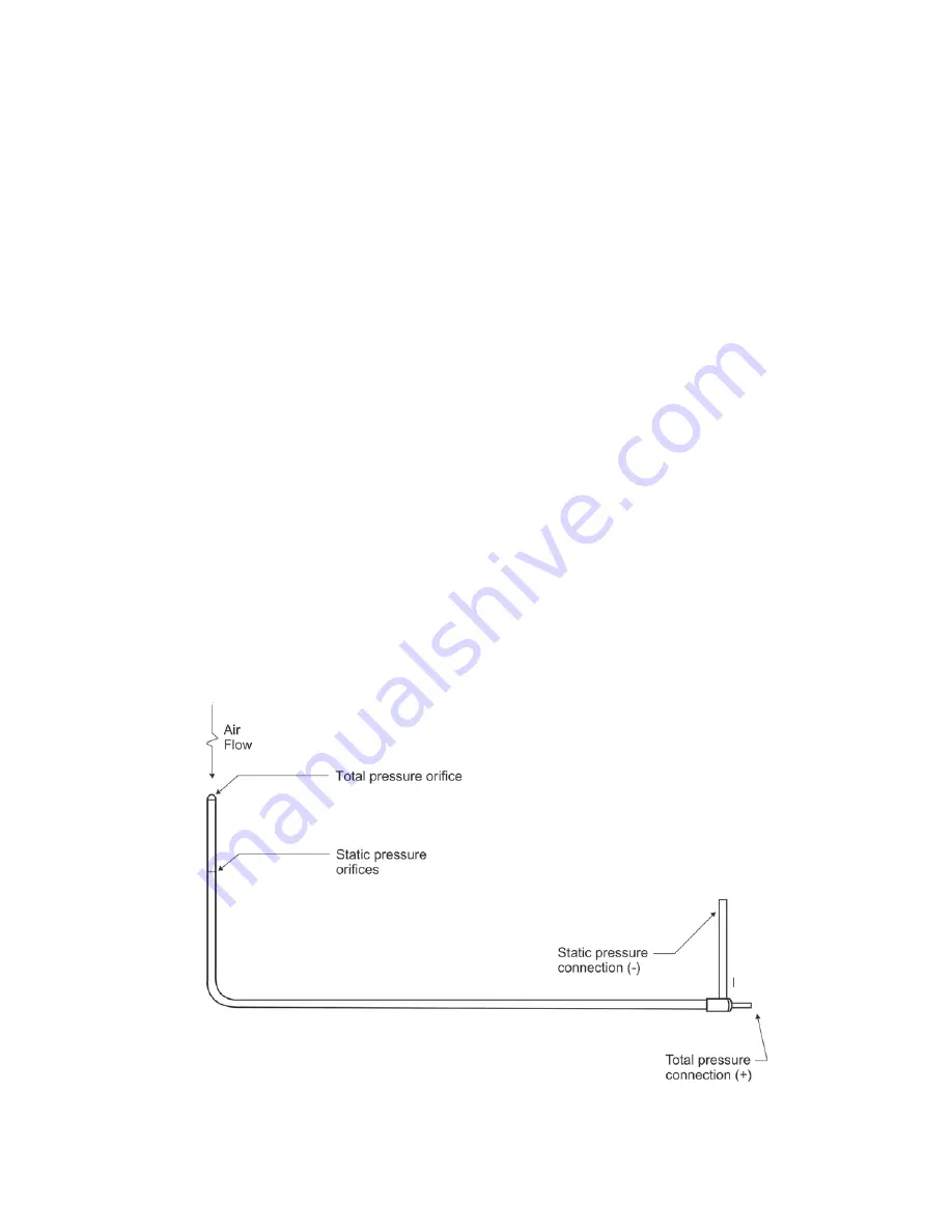
The pitot tube is primarily used to obtain air velocity measurements in ductwork. A pitot tube is stainless steel with a 90
degree bend at one end and two connectors at a 90 degree angle located near the base. The measurement range of the
AirData Multimeter with the pitot tube is 25 to 29,000 fpm (calibration accuracy is certified from 50 to 8,000 fpm). A
"traverse" of the duct is obtained by taking multiple air velocity readings at equal area locations within the duct cross-section.
See AIR BALANCE MANUALS AND TRAINING PROGRAMS for sources of detailed information on performing duct
traverses and other air balance procedures. The stainless steel pitot tube included in the AirData Multimeter kit is suitable
for use in temperatures up to 1500
/
F.
FIGURE 6.1 PITOT TUBE
Содержание AIRDATA ADM-880C
Страница 42: ...ADM 880C 07 20 09 37 FIGURE 6 3 VELGRID ASSEMBLY...
Страница 50: ...ADM 880C 07 20 09 45 FIGURE 10 1 FRAME STORAGE FIGURE 10 2 FLOWHOOD IN CASE...
Страница 51: ...ADM 880C 07 20 09 46 FIGURE 10 3 FLOWHOOD ASSEMBLY...
Страница 53: ...ADM 880C 07 20 09 48 FIGURE 10 7 1X5 FRAME ASSEMBLY FIGURE 10 8 3X3 FRAME ASSEMBLY...


