background image

19

Intraoral Scanner User Manual

Separation distances

The

Aoralscan 2

is intended for use in the electromagnetic environment in which

radiated RF disturbances are controlled. The customer or the user of the

Aoralscan

2

can help prevent electromagnetic interference by maintaining a minimum distance

between portable and mobile RF communications equipment (transmitters) and the

Aoralscan 2

as recommended below, according to the maximum output power of the

communications equipment.

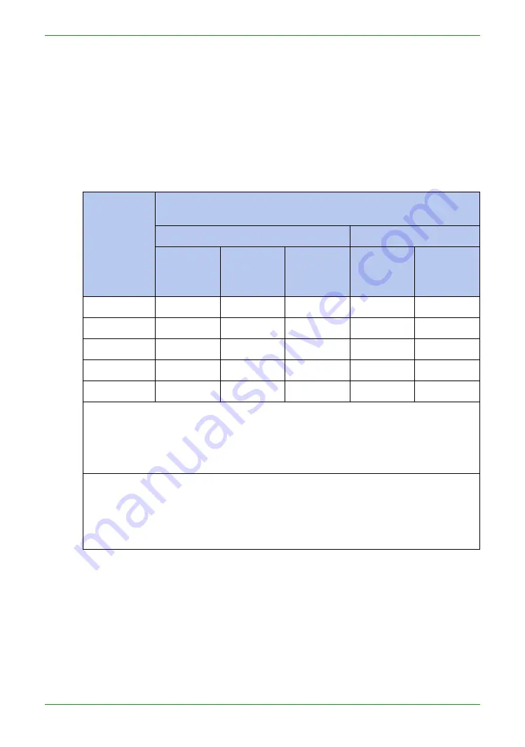
Table 2-5 Recommended separation distances between portable and mobile RF communications

equipment and the Aoralscan 2

Rated

maximum

output

power of

transmitter

(W)

Separation distance according to frequency of transmitter

(m)

IEC 60601-1-2 : 2007

IEC 60601-1-2 : 2014

150 kHz to

80 MHz

d

= 1.2

√P

80 MHz to

800 MHz

d

= 1.2

√P

800 MHz

to 2.5 GHz

d

= 2.3

√P

150 kHz to

80 MHz

d

= 1.2

√P

80 MHz to

2.7 GHz

d

= 2.0

√P

0.01

0.12

0.12

0.23

0.12

0.20

0.1

0.38

0.38

0.73

0.38

0.63

1

1.2

1.2

2.3

1.2

2.0

10

3.8

3.8

7.3

3.8

6.3

100

12

12

23

12

20

For transmitters rated a maximum output power not listed above, the

recommended separation distance

d

in meters (m) can be estimated using the

equation applicable to the frequency of the transmitter, where

P

is the maximum

output power rating of the transmitter in watts (W) according to the transmitter

manufacturer.

NOTE 1:

At 80 MHz and 800 MHz, the separation distance for the higher frequency

range applies.

NOTE 2:

These guidelines may not apply in all situations. Electromagnetic

propagation is affected by absorption and reflection from structures,

objects and people.

The medical electrical equipment is suitable for the professional healthcare

environment per 60601-1-2:2014. It is suitable for use in physician offices, clinics,

hospitals, and other professional healthcare environments except near HF surgical

equipment and the RF shielded room of an ME system for magnetic resonance

imaging or other environments where the intensity of electromagnetic disturbances is

high.
The clinical environments where the device can be used include physician offices,

clinics, hospitals, and clinical point-of-care for diagnosis of patients except

environments where the intensity of electromagnetic disturbances is high.

Содержание Aoralscan 2

Страница 1: ...t information 8 2 Safety information 9 Precautions 9 Legend of labels and symbols 11 On the device 11 On the carry box package 11 Compliance 13 FCC compliance statement 13 Electrical safety 13 EMC notice 14 Electromagnetic emissions 14 Interference immunity 15 Separation distances 19 3 Overview 21 Benefits of the product 21 ...

Страница 2: ...tware programs 27 4 Setting up the scanner 28 Connecting the scanner 28 Disconnecting the scanner 30 Calibrating the scanner 30 5 Scanning preparation 34 Scanning basics 34 Tooth preparation 34 Scanner preparation 34 Scanning position and path 35 Heating the scanner tip 35 6 Clinical case quick guide 37 Connection the scanner 37 Calibration 37 Create order 37 Scan upper jaw 38 Scan lower jaw 40 ...

Страница 3: ...aoralScan 46 Introduction to Dental Order System 47 Information 48 Order List 50 Setting 53 Data storage 56 Navigating IntraoralScan interface 56 Introduction to IntraoralScan function 62 Scan technique 62 Loading project 63 Dental Order System 64 Scan Upper Lower Jaw 64 Scan Upper Jaw Lower Jaw Implant 69 Scan Total Jaw 72 Pre design 77 Upload Order 86 8 Using Dental Cloud 88 ...

Страница 4: ...2 Management cases 92 Order status process 93 9 Care and maintenance 97 Pre cleaning disinfection and sterilization 97 Scanner cradle care 98 Scanner body care 99 Scanner tip care 101 Scanner storage 106 Storage for transport 106 Daily and long term storage 106 10 Hardware specification 107 Specifications 107 Environmental requirements 108 ...

Страница 5: ...g3D Corporation All rights reserved No part of this publication may be reproduced transmitted transcribed stored in a retrieval system or translated into any language or computer language in any form or by any means electronic mechanical magnetic optical chemical manual or otherwise without the prior written permission of Shining3D Corporation All other logos products or company names mentioned in...

Страница 6: ...ted by the patients themselves Do not misuse the scanner and do not use or operate the software programs incorrectly The clinical environments where the scanner and the software programs can be used include dental clinics dental hospitals and dental laboratories Only trained medical personnel may use the scanner and the supplied software programs Installation use and operation of the scanner are s...

Страница 7: ...ll outlets The device should not be used adjacent to or stacked with other equipment If adjacent or stacked use is necessary the device should be observed to verify normal operation in the configuration in which it will be used WEEE Disposal of Waste Electrical and Electronic Equipment and by users in private households in the European Union This symbol on the product or on the packaging indicates...

Страница 8: ...orm specific tasks properly preventing unnecessary errors This icon marks NOTE S additional information for particular situation This icon marks CAUTION S improper actions or conditions that may damage the product or injury and consequently void your warranty or service contract or lose the patient data or system data This icon marks WARNING S the safety instructions that you must precisely follow...

Страница 9: ...ained in this chapter Operating the hardware and software without a proper awareness of safe use could lead to fatal damage to the hardware or permanent data loss Ensure that the connection is performed correctly by following the instructions given in Connecting the scanner on chapter 4 Use only medical grade devices with the scanner in the patient environment The hardware and software should only...

Страница 10: ...with care and avoid hitting or scratching the surfaces as it contains fragile components Dropping the scanner on the floor may cause permanent damage If you accidentally drop the scanner you MUST dispose of the scanner tip immediately and do not use the same tip again The mirror in the tip might shatter into small pieces and using it again poses the highest risk of causing serious injury to the us...

Страница 11: ...warning caution Indicates that the device complies with requirements for the BF type applied part according to IEC 60601 1 providing protection against electric shock On the carry box package Table 2 2 Labels and symbols on the carry box package Symbol Explanation General warning caution Indicates that the device complies with requirements for the BF type applied part according to IEC 60601 1 prov...

Страница 12: ...re Indicates that the transport package shall be kept dry Indicates correct upright position of the transport package Indicates the stack limits A maximum of 6 units of identical packages may be stacked Indicates temperature limits The product must be stored in the original shipping package in environments between 25 C and 60 C Indicates the humidity limits The product must be stored in the origin...

Страница 13: ...luding interference that may cause undesired operation Electrical safety Only trained medical personnel should operate this scanner The product complies with the following standards Electrical IEC 60601 1 2 2014 IEC 60601 1 2015 A1 2012 ed 3 1 IEC 60601 1 6 2013 Con Ed 3 1 Rev October 29 2013 IEC 62366 1 2015 IEC 62304 2006 AMD1 2015 Classification Type of protection against electric shock Class I...

Страница 14: ...ectromagnetic tables The Aoralscan 2 is intended for use in the electromagnetic environment specified below The customer or user of the Aoralscan 2 should assure that it is used in such an environment Table 2 3 Guidance and manufacturer s declaration electromagnetic emissions Emission measurement Conformity Electromagnetic environment guidelines RF emissions CISPR 11 Group 1 The Aoralscan 2 uses R...

Страница 15: ...IEC 61000 4 2 8 kV contact 15 kV air 8 kV contact 15 kV air Floors should be wood concrete or ceramic tile If floors are covered with synthetic material a relative humidity of at least 30 is recommended Electrical fast transient burst IEC 61000 4 4 2 kV for power supply lines 1 kV for input output lines 2 kV for power supply lines 1 kV for input output lines Mains power quality should be that of a...

Страница 16: ... typical commercial or hospital environment If the user of the Aoralscan 2 requires continued operation during power mains interruptions it is recommended that the Aoralscan 2 be powered from an uninterruptible power supply or a battery Power frequency 50 60 Hz magnetic field IEC 61000 4 8 30 A m 30 A m Power frequency magnetic fields should be at levels characteristic of a typical location in a t...

Страница 17: ...smitter Recommended separation distance d 1 2 P IEC 61000 4 6 Radiated RF IEC 61000 4 3 6 Vrms 150 kHz to 80 MHz in ISM bandsc 3 V m 80 MHz to 2 7 GHz 6 Vrms 3 V m IEC 60601 1 2 2007 d 1 2 P 80 MHz to 800 MHz d 2 3 P 800 MHz to 2 5 GHz IEC 60601 1 2 2014 d 2 0 P 80 MHz to 2 7 GHz Where P is the maximum output power rating of the transmitter in watts W according to the transmitter manufacturer and ...

Страница 18: ...ich the Aoralscan 2 is used exceeds the applicable RF compliance level above the Aoralscan 2 should be observed to verify normal operation If abnormal performance is observed additional measures may be necessary such as reorienting or relocating the Aoralscan 2 b Over the frequency range 150 kHz to 80 MHz field strengths should be less than 3 V m c The ISM industrial scientific and medical bands b...

Страница 19: ...r transmitters rated a maximum output power not listed above the recommended separation distance d in meters m can be estimated using the equation applicable to the frequency of the transmitter where P is the maximum output power rating of the transmitter in watts W according to the transmitter manufacturer NOTE 1 At 80 MHz and 800 MHz the separation distance for the higher frequency range applies...

Страница 20: ...to any part of the Aoralscan 2 including cables specified by the manufacturer Otherwise degradation of the performance of this equipment could result If higher IMMUNITY TEST LEVELS than those specified in IEC60601 1 2 Table 9 are used the minimum separation distance may be lowered Lower minimum separation distances shall be calculated using the equation specified in IEC60601 1 2 Chapter 8 10 ...

Страница 21: ...porting the scan data in STL OBJ format to CAD CAM systems for different purposes of dental care Carry box list Check the carry box for the following items If any item is missing or damaged contact your place of purchase immediately 1 1 x Intraoral Scanner with a USB 3 0 upstream cable length 2 meters 2 1 x scanner cradle 12 Vdc 1 67 A 3 1 x protection cap 4 2 x scanner tip 1 is already attached t...

Страница 22: ...t or compromise the safety of the grounding scheme Using accessories or power supply units other than those specified may cause the warranty to void and result in increased emissions decreased EMI immunity of the device or even damages to the device and personal injuries Use of other accessories results in non compliance Always store the 2 in 1 USB dongle in a safe place for later use NOTE We reco...

Страница 23: ...n how to use these software programs see Using IntraoralScan on chapter 7 System requirements Before installing and running the supplied software programs your computer shall meet the following requirements Table 3 3 System requirements CPU Intel Core i7 8700 or higher Memory 16 GB or higher Hard drive 1 TB SATA Hard Drive 7200 RPM 6 0 Gb s or higher Graphic card GPU NVIDIA GTX 1070 6GB DDR3 or hi...

Страница 24: ...ner to be dissipated from the case 4 Intake vent Allows the ambient cool air to enter into the case to help cool down the heat produced by the operation of scanner NOTE When scanning do not hold the scanner in the way that covers or blocks the intake and exhaust vents Otherwise the scanner may become overheated 5 LED ring light Indicates the status of your scanner Blinking green the scanner is in ...

Страница 25: ...r switch To receive power from the power outlet turn it on to stop receiving power from the power outlet turn it off 4 Power connector Connect the power plug from the supplied power adapter to this power connector and plug the power adapter to the power outlet 5 USB 3 0 downstream port For connecting the scanner cradle and the USB port of your computer using the supplied USB cable This port transf...

Страница 26: ...e To lower the temperature inside scanner body the cooling fan still operates for about 30 minutes after the scanner goes into standby or sleep mode Then it will stop spinning The scanner tip is being heated whenever power is supplied even if the scanner is in standby or sleep mode USB cable storage To prevent the USB cable from getting damaged by excessive bending or twisting you should loosely c...

Страница 27: ...r on chapter 4 for more necessary procedures to get started Follow the steps below to complete the installation of software programs 1 Insert the supplied 2 in 1 USB dongle into the USB port of your computer 2 Find the file named IntraoralScanX X X X exe and run it as administrator 3 The IntraoralScan InstallShield Wizard window appears to start the installation 4 Specify a language from the drop ...

Страница 28: ...ironment or in the areas of temperature extremes or in direct sunlight Prepare a flat surface e g your desk for the scanner and the cradle Do not place them on a slanted surface Before the installation is completed do not plug the power adapter into the wall outlet or turn on the scanner until you are instructed to do so Always return the scanner to the cradle when it is not in use Do not place th...

Страница 29: ...the supplied power adapter into the power connector on the cradle and plug the power adapter into a wall outlet 3 Connect the scanner cable to the USB 3 0 upstream port on the cradle 4 Connect the USB 3 0 downstream port on the cradle and your computer with the supplied USB 3 0 cable 5 Insert the supplied 2 in 1 USB dongle into the USB port of your computer 5 3 4 2 6 Turn on the power switch on th...

Страница 30: ...any sharp bends in the cable after you disconnect the scanner See USB cable storage on chapter 3 for more details Calibrating the scanner Under these circumstances we recommend that you shall execute the calibration for the scanner to ensure the accuracy of scanned data The initial setup of the scanner is completed The scanner has been used for a period of time e g 2 weeks The scanner is accidenta...

Страница 31: ...n the mirror of the tip when detaching as this may result in damage to the mirror Store the detached tip in a safe place e g a dental instrument tray for future use 7 Connect the on the supplied Calibrator and your computer with the supplied USB 3 0 cable 8 Gently slide the Calibrator onto the front end of the scanner as illustrated 9 Double click the shortcut icon of IntraOralCalibration Display ...

Страница 32: ...essage would be popped So make sure the scanner be plugged into the calibration firmly before next operation 11 Click Start The status bar shows the percentage of completion NOTE It is normal that the calibration takes approximately 5 minutes 12 The following message appears once the calibration is completed Click OK to exit ...

Страница 33: ...scanner CAUTION Make sure that the Calibrator is removed from the scanner after the calibration is done Otherwise the Calibrator may get very warm 14 Re attach the scanner tip to the scanner for later use or put the protection cap onto the scanner to prevent damage and dust ...

Страница 34: ...the tongue still and move it to the opposite side of the mouth Dry the teeth thoroughly before starting a scan When scanning consider using the saliva ejector and tampons to keep the surfaces of teeth dry If necessary consider using the retractors to avoid excessive tissue from being scanned If necessary consider using tampons to help create space while working on narrow regions between teeth Scan...

Страница 35: ...scan data of a single area includes the surfaces of occlusal lingual buccal interproximal contacts of the adjacent teeth and 2 3 mm buccal gingiva A complete scan data of a single case includes the lower jaw upper jaw and bite registration When scanning change the scanning angle to 35 55 degrees in order to create overlaps It is important to achieve an overlap of at least 30 between each acquisiti...

Страница 36: ...anner tip is lower than the set point for anti fogging a notification message of pre heating and current temperature appears When the message disappears the warm up is done The scanner is now ready for an acquisition NOTES The heater maintains constant temperature on the scanner tip The scanner tip is being heated whenever power is supplied even if the scanner is in standby or sleep mode If the he...

Страница 37: ...it is necessary to perform calibration periodically recommended every 15 days Create order Double click desktop icon and the software will open the Dental Order System Click Project and select New to create a new order Fill out the necessary order information including the names of dentist s patient and lab s Or select Load to open an existing project Select the desired type of restoration and the...

Страница 38: ...rm that the image of the camera window in the upper right corner of the software is displayed normally Click the Scan button or the space bar to start scanning If it prompts Please remove the scanner from the tooth for optimization then remove the scanner for data optimization and continue scanning after optimization is completed ...

Страница 39: ... head to scan the data displayed in the red frame If there is more buccal tongue side data during the scanning process it is recommended to press the pause button to automatically delete as shown below effect image before and after pause Confirm that the model scan is complete click the Finish button or long press the space bar to process and save the data After the completion the upper jaw icon i...

Страница 40: ...an total jaw The lower jaw finish scan data processing ends and automatically jumps to the full jaw scan procedure Click the scan button or the space bar to start scanning After scanning some data the software automatically performs dynamic bite stitching as shown below If the upper and lower jaw data and the full jaw data are occluded properly click or space bar to pause the scan to see the bite ...

Страница 41: ...ral Scanner User Manual Confirm that the bite effect is appropriate Click the Finish button or long press the space bar to post process the data View result data View result data in IntraoralScan View upper jaw ...

Страница 42: ...42 Intraoral Scanner User Manual View lower jaw View the occlusal effect ...

Страница 43: ...43 Intraoral Scanner User Manual View data storage path Click the button to return to the order interface and click to open the folder path of the current order storage ...

Страница 44: ... in the software will prompt No login to the account go to the setup interface to log in select Yes to open the Configure Account interface Register the account on the webpage of the dental cloud add the lab refer to Chapter 9 Registering Account and Building Relationship Network Then return to the Dental Order System login account after the login is successful upload the order ...

Страница 45: ...45 Intraoral Scanner User Manual ...

Страница 46: ...creation editing searching scanning and deletion as well as uploading downloading previewing and tracking of scanned order and data The scan module collects oral digital images processes rendering data and outputs 3D data STL OBJ Note To run software the following requirements must be met The supplied 2 in 1 USB dongle is plugged into the USB port of your computer The connection between the scanne...

Страница 47: ...Introduction to Dental Order System Double click the desktop icon open the software to dental order system the interface is as follows The dental order system is mainly composed of three parts 1 order information 2 order list 3 setting ...

Страница 48: ... the new order with the completed order information Explore Open the folder where the saved order is located Scan Start scanning Preview After the order scan is completed the scanned data is viewed through the DentalViewer Upload After the order scan is completed the current order data is uploaded to the dental cloud ...

Страница 49: ...s button you need to set the path of the EXOCAD design software first 2 Order Type Restoration and Ortho 3 Order Information Set the order number doctor patient lab and notes information 4 teeth map Left mouse button to select the tooth position Right mouse button to cancel the defined repair type Ctrl left mouse button copy the repair type defined by the previous tooth position to the currently s...

Страница 50: ...ts the order status of all orders under the dental order path 1 Refresh Refresh the order list 2 Import Order Import orders that are not stored in the order path If the import is successful it will be displayed in the first line of the list If an order with the same name already exists in the order path the imported order is automatically renamed to source order name _import_ 3 Search Search by or...

Страница 51: ...the lab is making The right click menus or operate icons for such orders are Load Open in Explore Duplicate Delete Download Design Request Re design Delivering The lab has shipped the goods and the doctor has not received the order for the goods The right click menus or operate icons for such orders are Load Open in Explore Duplicate Delete Download Design Delivery Information Confirm Received Req...

Страница 52: ...der Delete the currently selected order form the order list you can choose whether to delete stored order files and scaned data Upload the currently selected order to the dental cloud Order data has been uploaded to the dental cloud and the doctor has cancelled the currently selected order Download Design Confirm Design Request Re design Delivery Information Request Re delivery ...

Страница 53: ...e Generate thirdParty xml under the order path The third party design software can import the order and directly design The default is off 3 User interface language User setting software interface language Chinese Simplified and English The default language is the language selected during software installation 4 Dental Notation FDI World Dental Federation notation and Universal numbering system th...

Страница 54: ...er ID C Naming Rule items Order ID Date Doctor Code Patient Code lab Code Order Number Doctor Name Patient Name lab Name D Save Save the current setting E Cancel Cancel and discard the current setting NOTE After modifying the setting user interface language Dental Notation EXO DentalACD Path Dental Order path Order File Naming Rule information click Apply button show the New setting will take effe...

Страница 55: ... link to go to the dental cloud website to register Forget password Forgot your password click this link to go to the Dental Cloud website to retrieve your password Login Fill in the correct account and password login is successful and the contact information filled in during registration is displayed in the upper left corner of the software mobile phone account first select the area then enter th...

Страница 56: ...by default in C DentalOrder named by date as shown below Navigating IntraoralScan interface In the Dental Order System created order saved it and will scan If no scanner is connected an error message appears to remind you to check and reconnect the scanner NOTE If the scanner is connected yet the error message appears remove then reconnect the scanner If IntraoralScan still cannot detect ...

Страница 57: ... to bottom respectively Fit View button Click this button to restore the default size of the model Rotate button After clicking the button press and hold the left mouse button to rotate the model Move button After clicking the button press and hold the left mouse button to pan the model Vew Lock button When this button is clicked the automatic view tracking function is enabled during scanning Sele...

Страница 58: ...d lower jaws are reversed during scanning Refined Area button Select the refined area and perform refinement processing after post processing 5 Scan menu scan start pause shortcut space bar reset and complete Scan Click the button to start scanning after starting the scan the icon changes to indicate that the scan is in progress if the scan is completed click the scan button again to perform the s...

Страница 59: ...t processing data processing is more elaborate and enhances the data details Auto Gain The default is to adjust the gain automatically If the Auto Gain check box is not checked you can manually set the gain by dragging the slider or entering a value Manually set the dental scan gain recommendation 0 2 Intraoral Scan gain is recommended to be 8 Cut By default it is read from the camera You can also...

Страница 60: ...non scanning Icon Example Description Connecting Connected Not connected Connection error Standby Overheat Sleeping mode During the scanning process the number of scanning frames is displayed here 10 3D View Displays the 3D model data acquired by the scan Support the left mouse button to rotate the 3D model and the right mouse button to translate the 3D model data 11 The software supports the IMU ...

Страница 61: ...e forearm to the center keep the scanner head up and at an angle of more than 45 degrees with the horizontal plane for 0 5 seconds the software will perform the view enlargement operation When the wrist moves the forearm to the left right keep the scanner head tilted to one side and form an angle of 45 degrees or more with the horizontal plane for 0 5 seconds The software will perform the view rot...

Страница 62: ...ftware has certain requirements During the scanning process the speed cannot be too fast and the model can be scanned to move to the next part to scan During the scanning process when scanning the previous area the next area the back side and the front side there must be a certain overlap area otherwise the scanned model may have accumulated errors The scanner adopts S type scanning and the follow...

Страница 63: ...n Figure b S type scanning Loading project Load the unscanned order that is the post processing is not completed open Intraoral Scan pop up message Click OK to continue the last scan and the full jaw data must be rescanned Click Cancel to restart scanning After loading and processing the completed order open Intraoral Scan pop ...

Страница 64: ...scanning Dental Order System Click the icon to return to the dental order system and view create edit the order Scan Upper Lower Jaw Scan To enter the jaws scanning process first check whether the image display in the image window is normal After confirming the normal click the button or the space bar to start scanning ...

Страница 65: ...65 Intraoral Scanner User Manual Figure 1 Scanning process to support edge sweep optimization ...

Страница 66: ... can click the or space bar to pause the scanning and delete the buccal and lingual data in the mouth during the pause to facilitate the user to check the tooth sweeping situation Click again to continue scanning Rescan If the scan data is not satisfactory you can re scan it Click the button to pop up a prompt message box ...

Страница 67: ...ng is completed do not exit scan software interface and click scan button to re scan the data Scanning Completed After confirming that the model scan is completed click the Finish button or long press the space bar to save The green icon in the upper right corner of the icon as shown below indicates that the scanning process is finished ...

Страница 68: ...the order the prompt box Do you want to confirm the scan completed is displayed If you select Yes this order can no longer add scanning Note The maximum number of frames for the upper lower jaw scan is 3 000 frames When scanning to 2 500 frames it will prompt whether to stop scanning or continue to scan 500 frames ...

Страница 69: ... of dental restoration as the type of planting The scanning process has increased the process of scanning the implant Scan the lower jaw first without Intraoral Scan bar After the lower jaw scan is complete directly enter the scanning lower jaw implant interface and select the implant area and delete ...

Страница 70: ...70 Intraoral Scanner User Manual Figure 1 Selecting the implant area ...

Страница 71: ...71 Intraoral Scanner User Manual Figure 2 Delete Click the button to enter the scanning implant process must bring the planting rod before scanning ...

Страница 72: ...72 Intraoral Scanner User Manual Figure 3 Scanning planting rod Figure 4 Post processed implant data Scan Total Jaw After the lower jaw scan is completed and saved it automatically proceeds to the next ...

Страница 73: ...can are made You can stop scanning after connecting The maximum number of frames in the whole jaw is 800 frames Scanning to 300 frames will prompt whether to stop scanning or continue to scan 500 frames An example of scanning a full jaw the purple on the left is the data of the full jaw of the scan and the tan is the result of the upper and lower jaws Scan a two piece full jaw example scan pause s...

Страница 74: ...74 Intraoral Scanner User Manual ...

Страница 75: ...75 Intraoral Scanner User Manual Scan a three piece full jaw example ...

Страница 76: ...76 Intraoral Scanner User Manual Stitching effect after software post processing texture effect and non texture effect map ...

Страница 77: ...nner User Manual Pre design Scanning data is added to the design software in order to make it easier to use in the design software Users can skip this process and upload orders directly This process has five functions ...

Страница 78: ...rd pointing to the observer Y to the right observer s perspective positive on the Z axis forming the right handed coordinate system 2 Mark Teeth used to manually mark the corresponding position of the tooth specified in the order in the scanning model for subsequent extraction of the Margin line and viewing the undercut 3 Extract Margin line used to extract and save the Margin line of the marked c...

Страница 79: ...ow Rotate the data with the left mouse button and right click the data to adjust the position of the jaw Click the button to confirm and save the current adjustment result Click the button to cancel and discard the current adjustment result and exit the adjustment coordinate process Mark Teeth Click on the button under the Pre design process to enter the marker tooth position interface and the too...

Страница 80: ...k the Finish Teeth Marking button to confirm and save the current tag Click the Cancel Teeth Marking button to cancel and discard the current marker and exit the marker toothing process Extract Margin line Click the button under the Pre design flow to enter the extract margin line interface Double click on a Margin line of a tooth to select four points the system automatically draws the Margin lin...

Страница 81: ...81 Intraoral Scanner User Manual Figure 1 Double click to select four points Figure 2 Automatically drawing the Margin line ...

Страница 82: ...th and its Margin line Next Tooth switches to the next marked tooth and its Margin line Delete Delete a node if some node on the Margin line is selected If no node is selected the Margin line of the current tooth is deleted Cancel And Exit abandon the extracted Margin line and exit the process of extracting the Margin line Finish And Save confirms and saves the extracted Margin line and exits the ...

Страница 83: ...83 Intraoral Scanner User Manual undercut area ...

Страница 84: ... upper and lower jaw switching Generate Undercut shows the undercut effect Finish Undercut exit the undercut process Check Bite Click the button under the Pre design process to enter the check bite interface Green indicates the distant area of the two jaw teeth red indicates the collision area of the two jaw teeth and blue indicates the bite area of the two jaw teeth ...

Страница 85: ...85 Intraoral Scanner User Manual Figure 1 Two jaw tile effect ...

Страница 86: ...ave up the adjusted bite relationship and exited the test bite process Finish And Save saves the adjusted snap closure and exits the detection bite process Upload Order When uploading the order for the first time in Intraoral Scan it will prompt You have not logged in to the account Whether to direct to the setting interface to log in select Yes to open the Configure Account interface See the Uplo...

Страница 87: ...87 Intraoral Scanner User Manual Dental Manager Pro for details ...

Страница 88: ...cs and doctor users you can manage order cases manage organizations and maintain account information Visit the website http dental shining3d com Register Account To register for the dental cloud account click the Register link to go to the dental cloud website to register It is recommended to open the dental cloud website using browsers such as Chrome Firefox and Apple Click Login in the top right...

Страница 89: ...log in directly after registration I am a lab registered dental laboratory and administrators After registration is successful you need to wait for the system administrator to review before you can log in Note that this type of account can only be used on the web side and cannot be used on the desktop client Fill in the real application information according to each content the notification of inf...

Страница 90: ...Manual After the registration is successful the page automatically jumps to the login interface enter the correct mailbox or mobile phone number and password you can set the remember password to facilitate subsequent quick login ...

Страница 91: ...the upper right corner of the interface to create a new network 1 User Select the user himself 2 Lab Select a cooperative from the drop down list 3 Submit Submit the newly created network The submission is successful and is displayed in the page list The relationship status of the newly created relationship is to be confirmed You need to wait for the lab to accept the confirmation the relationship...

Страница 92: ...ail This member s e mail is also the account that the e mail is logged in The default password for login is 888888 5 Is Admin Set whether it is an administrator The default is No 6 Submit Fill in the information and submit the member successfully Delete member Select the member you want to delete and click the Delete button to confirm the deletion Management cases The account is successfully logge...

Страница 93: ...page Order status process The order is transferred between the hospital clinic doctor and the laboratories and the two parties cooperate to advance the entire process from one visit to completion of treatment The doctor operates in the client Dental Manager Pro and the lab operates on the web page side The most common flow chart for uploaded order status is as follows ...

Страница 94: ...e the previous section for details 2 The lab refused to accept the order the lab of the lab refused to accept the order 3 The lab received the order the lab of the lab confirmed the order 4 The design plan uploaded by the lab the lab of the lab uploads the design plan including the documents and data ...

Страница 95: ... and the doctor can download the design plan in the client Dental Manager Pro The design data is saved by default in the DesignData folder of the order catalog If the design plan is approved the doctor confirm Design and the order status is Making if not the doctor Request Re design fills in the design requirements and the order status is Accepcted which requires the lab to redesign the plan uploa...

Страница 96: ...fice is completed and the logistics information is submitted and delivered The order status is Delivering 8 Doctor confirmed the receipt After the lab delivers the goods the doctor can view the logistics information and confirm the receipt after receiving the goods The order status is Finished If the doctor does not receive the goods or the goods have problems request re delivery the order status ...

Страница 97: ...ilized Follow the instructions prior to initial use Ensure you have completely disconnected the power supply and all connections from the scanner Follow the instructions given in this User Manual to pre clean disinfect and sterilize each part of the scanner Using other methods not approved by Shining3DCorporation will damage your scanner and void your warranty Using detergent disinfection solution...

Страница 98: ...lized the scanner body scanner cradle and scanner tip before each scan The caring methods for the scanner cradle scanner body and scanner tip are different and must be executed separately After disinfecting the scanner cradle you may proceed with the scanner body and finally the scanner tip See Scanner body care on chapter 9 and Scanner tip care on chapter 9 for details Ensure that the scanner bod...

Страница 99: ...care on chapter 9 for details Ensure that the scanner tip is detached from the scanner and the protection cap is put on the scanner when disinfecting the scanner body Follow the steps below to complete the disinfection 1 Disconnect the power of the Aoralscan 2 see Disconnecting the scanner on chapter 4 2 Hold the scanner tip firmly with your thumb and forefinger on both sides and then gently slide...

Страница 100: ...jects or other such tools which may result in scratches and damage to the scanner 6 Hold the scanner body with your hand 7 Use new cotton gauze moistened with 70 75 solution of ethanol to wipe the surface of scanner body CAUTIONS Avoid using detergent of any kind as some detergents or surfactants might penetrate into the surface of the scanner body Do not clean the intake and exhaust vents with an...

Страница 101: ...p into the disinfectant solution be sure to follow the instructions on the disinfectant label and limit the time and depth that the tip is soaked within the minimum time recommended The scanner tip can be sterilized up to 20 times and must be disposed of afterwards For more information on disposal see Disposal on chapter 1 High level disinfection and steam sterilization must NOT be combined Apply ...

Страница 102: ...spect the mirror of the tip to ensure that the mirror is not cracked or broken and there is no scratch on it CAUTION If the mirror of the tip has cracks or scratches stop the cleaning process and contact your local distributor or service provider 6 Gently clean the inner and outer sides of the tip using mild pH neutral soap water and a soft brush for 3 minutes When cleaning the inner surface of th...

Страница 103: ... thoroughly before use CAUTIONS To avoid possible damage use the disinfection solution verified by Shining3D Corporation and specified here only Once a spill occurs follow disinfectant manufacturer s handling instructions 13 Immerse the cleaned tip into the disinfectant and leave it for at least 12 minutes at 25 C 25 C 12 min 14 Prepare a large container of sterile water e g 2 L 15 Take out the ti...

Страница 104: ...canner on chapter 4 2 Hold the scanner tip firmly with your thumb and forefinger on both sides and then gently slide the scanner tip off from the scanner as illustrated CAUTION Do not place your finger s on the mirror of the tip when detaching as this may result in damage to the mirror 3 Hold the supplied protection cap with the triangle mark facing upward Then align the protection cap blocks to t...

Страница 105: ... not damaged during the cleaning process 12 Wrap the cleaned tip with a cloth cautiously 13 Place the wrapped tip in the autoclave and sterilize it at 121 C and with 1 5 atm pressure for at least 30 minutes 14 Dry the sterilized tip for 30 minutes with the autoclave program before opening the autoclave 15 Re attach the scanner tip see Attaching the scanner tip on chapter 9 Attaching the scanner ti...

Страница 106: ... scanner is clean and sterile before placing it in the original carry box package to avoid any possible contamination Place each part of the product e g the tip scanner body cradle power adapter in the original package carefully and prevent kinks of the cable Make sure that each cable is rolled up and tangle free before placing it in the original carry box Before closing the lid make sure no part ...

Страница 107: ...ld 11 mm x 11 mm Scan principle Non contact scanner with the DLP structured light Dimension Length 280 mm Width 40 mm Height 55 mm Weight 325 g without cable Output STL OBJ Connector USB 3 0 Power Input 5 Vdc 2 A Cradle Dimension Length 265 mm Width 82 mm Height 55 mm Weight 900 100 g Power Input 12 Vdc 1 67 A Product life 3 years ...

Страница 108: ...l requirements Operating and storage requirements Operating temperature 10 40 C Storage Transport temperature 25 C 60 C Operating altitude 3000 M Storage Transport Relative humidity 30 75 MTBF 14 600 hrs except DMD LED Air pressure 700 hPa 1060 hPa ...

Отзывы: