


7
Installing and Adjusting
the Bar and Chain
Never attempt to install,
replace, or adjust the chain
while the engine is running.
WARNING!
1. Using the small end of the plug wrench,
remove the sprocket covernut (turn
counterclockwise to remove) and
remove the sprocket cover.
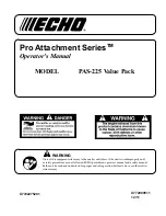
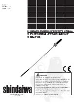
Installing Tool Attachment
1. Place Multipurpose Engine and the
Splitboom Attachment SBA-P4 on a
clean, flat surface so that both assem-
blies fit end to end. The powerhead
assembly should be facing up, and the
Splitboom Attachment SBA-P4 should
be positioned with the locking hole in
the tube end facing up.
CAUTION!
Keep the open ends of the tubes clean
and free of debris!
. Slip off the protective cover from the
end of the tool, and loosen the coupler
screw knob.
3. Insert the tube into the coupler, with
the tool decal facing up, until the line
of the decal is flush with the end of the
coupler. Twist the tool back and forth
until you are sure it snaps in place by
the coupler latch.
Multipurpose
Tool Carrier
Latch Protector
(extended)
Latch
Locking
Hole
Coupler
Coupler
Screw
Knob
Splitboom
Attachment
SBA-P24
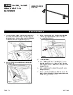
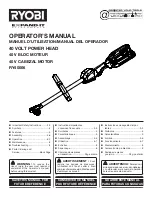
4. When the two tube halves are locked
together, press down on the spring-
loaded latch protector and tighten the
coupler screw.
CAUTION!
Make sure there is no gap between the
Latch Protector and the Coupler.
Coupler
Coupler Screw
Knob
Latch Protector
(lowered)
Disassembling The Pole
Sections
1. Place the unit on a clean, flat surface,
loosen the coupler screw. The spring
loaded coupler protector should pop up.
. Press down on the latch with your finger
or thumb. This releases the coupler
lock.
3. Pull the tube out of the coupler.
Press Latch
(continued)
The saw chain is very sharp.
Wear gloves to protect your hands
when handling.
WARNING!
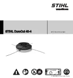
NOTE:
For the longest chain life, let new or
replacement chain loops soak in oil overnight
before installation.
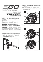
. Place the guide bar over the guide
bar adjustment stud on the cutting
assembly. Align the chain tensioning pin
with the hole in the guide bar.
Sprocket
Cover
Sprocket
Cover Nut
Installing and Adjusting
the Bar and Chain
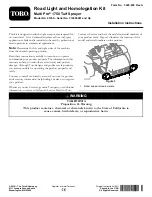
3. Install the chain loop over the drive links
within the guide bar groove, and then
align the chain over the drive sprocket.
Make sure the cutters
are properly oriented as
shown in this figure. If
the chain installation is
difficult or if the chain
appears too tight, refer
to the section “Adjusting
the Chain”.
Guide Bar
Guide Bar
Adjustment Stud
Guide Bar
Adjustment Stud
Chain Tensioning
Screw
Chain Tensioning
Pin
Chain Tensioner
Hole
4. Install the sprocket cover over the bar
stud. Using finger-pressure only, install
the sprocket cover nut.
5. Refer to the next page for chain
adjusting procedures.
Top of Bar
BAR
TIP
Bottom of Bar
Never operate the pole pruner
tool without the sprocket cover installed.
WARNING!
CAUTION!
Failure to align the guide bar and
chain tensioning pin can cause serious
damage to the sprocket cover, guide
bar, chain tensioning pin, and cutting
assembly.
Содержание SBA-P24
Страница 42: ...Italiano NOTA IT_14 ...
Страница 43: ...Italiano NOTA IT_15 ...