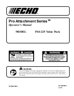


Pro Attachment Series
TM
Operator's Manual
MODEL
PAS-225 Value Pack
wArning
Users of this equipment risk injury to themselves and others if the unit is used improperly and/
or safety precautions are not followed. ECHO provides an operator’s manual and a safety manual.
Both must be read and understood for proper and safe operation. Failure to do so could result in
serious injury.
X7722275201
X772000511
12/11