


Chapter 7 Operator Control and Display Panel
40
Shield M10U user manual
Chapter 7 Operator Control and Display Panel
This chapter introduces the functions and operation instructions of the UPS operator control and display panel in
detail, and provides LCD display information, including LCD display types, detailed menu information, prompt
window information and UPS alarm list.
7.1 Introduction
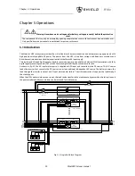
The operator control and display panel is located on the front panel of the UPS. Through the LCD panel, the operator
can operate and control the UPS, and check all measured parameters, UPS and battery status, event and history logs.
The operator control panel is divided into three functional areas as shown in
fig.7-1
: mimic current path, LCD display
& Menu, control and operation button. The detailed description of control and display panel is shown in
table.7-1
.
(a)
3-modules and 6-modules cabinet
(b)
2-modules and 4-modules cabinet
Fig.7- 1: UPS operator control and display panel
Table.7- 1: Description of UPS Operator Control and Display Panel
Indicator
Function
Button
Function
REC
Rectifier indicator(60kVA)
EPO
EPO (emergency power off)
BAT
Battery indicator(60kVA)
HOME
Back to main menu(90kVA)
BYP
Bypass indicator(60kVA)
Left arrow
Right arrow
Select main menu items;
switch between submenu;
increase or reduce for number
input(90kVA)
INV
Inverter indicator(60kVA)
ENTER
Confirm(90kVA)
OUTPUT
Load indicator(60kVA)
STATUS
Status indicator
Содержание M10U
Страница 1: ......
Страница 9: ......
Страница 71: ...Appendix B Power Connection of Modular System 62 Shield M10U user manual ...