


Chapter 3 Installation of UPS Rack System and Parallel Syste
m
Shield M10U user manual
21
3.2 UPS Rack Modules in Parallel System
The basic installation procedures of parallel system are the same with those of the UPS rack module system. In this
section, only the installation procedures related to the parallel system are introduced.
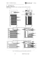
3.2.1 Installation of Cabinet
To make the maintenance and system test easier, an external maintenance bypass is recommended in the installation.
3.2.2 External Protective Devices
Refer to
Chapter 1 Installation
3.2.3 Power Cables
The power cable connection of the parallel rack module system is similar to that of the single UPS rack module system.
If the bypass input and rectifier input share the same neutral terminal and if an RCD protective device is installed at the
input, then the RCD device must be installed before the input cables are connected to the neutral terminal. Refer to
Chapter 1 Installation
Note: The length and specification of the power cables of each UPS module should be the same, including the bypass
input cables and UPS output cables, so that the load sharing effect can be achieved in bypass mode.
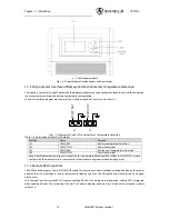
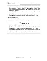
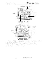
3.2.4 Parallel Signal Board
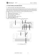
Installation of parallel signal board
The parallel signal board is installed at the rear of the cabinet. Shown as below:
CAN bus set
Communication ports
CAN bus
setting indicator
Fig.3- 2: Parallel Board
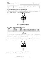
3-slots cabinet and 6-slots cabinet:
The switches SW1 and SW2 on the UPS should be set as below:
Single- all switches ON
2 paralleled- switch SW1 ON, switch SW2 OFF
3 paralleled- all switches OFF
2-slots cabinet and 4-slots cabinet:
No need to modify CAN bus setting.
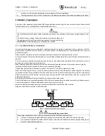
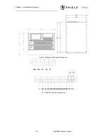
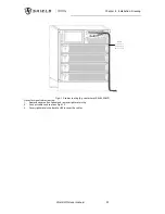
3.2.5 Control Cables
Parallel control cable
The parallel control cables are designed to be shielded and double insulated, DB15 terminals, and are connected between
the UPS rack modules to form a loop as shown below. The parallel signal board is installed at the rear of the cabinet. This
close loop connection ensures the reliability of the parallel system control. Refer to
fig. 3-3
Содержание M10U
Страница 1: ......
Страница 9: ......
Страница 71: ...Appendix B Power Connection of Modular System 62 Shield M10U user manual ...