


Chapter 1 Installation
Shield M10U user manual
5
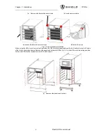
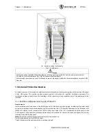
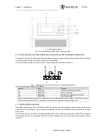
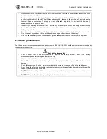
Bypass
module
Power
module
breakers
connector
Ellipse
cable
entry
Round
cable
entry
(d)
2 modules cabinet
Fig.1- 1: UPS Structure
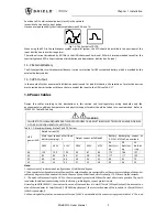
Table.1- 1: UPS Configuration List
Item
Component
Quantity
Remarks
1
System Display
1
Requisite, factory installed
2
Bypass module
1
Requisite, factory installed
3
Bypass/maintenance
bypass breakers
1
Requisite, factory installed
4
Power module
1 ≤n ≤6
Requisite
5
Decorative metal strip
2
Factory installed
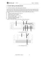
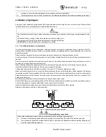
1.4.8 Installing Power Modules
The number and possible installation positions of the Power Modules may vary according to the chosen factory
configuration. Please install the power modules from bottom to top, so as to avoid cabinet toppling due to high gravity
center.
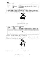
Installation procedures of power modules
When installing power modules always work from the lower available space upwards to prevent from raising the center
of gravity. The default setting from the bottom space upwards is NO.1 to NO.2 (2 modules cabinet), NO.1 to NO.3 (3
modules cabinet), NO.1 to NO.4 (4 modules cabinet), NO.1 to NO.6 (6 modules cabinet).
Notes
If installed as standalone unit, it’s recommended that install power modules from upper available space downwards
to prevent from corrosion of the bottom module.
Recover decorative metal strips on the two side of front panel. Loose screws through holes on metal strips,
pull
metal strips upwards
then take away the strips as
Fig.1-2(a)
.
Insert the module in the installation position, and push it into the cabinet.
Secure the module to the cabinet through the fixing holes on both sides of the front panel of the module.
Loose the upper and bottom 4 screws and fix two side decorative metal strips (as
Fig.1-2
) to cover the screws on
front side following
Fig.1-2(c)(d)
.
警告
危 险
Содержание M10U
Страница 1: ......
Страница 9: ......
Страница 71: ...Appendix B Power Connection of Modular System 62 Shield M10U user manual ...