


Chapter 1 Installation
Shield M10U user manual
1
Chapter 1 Installation
1.1 Introduction
This chapter introduces the relevant requirements for positioning and cabling of the Modular UPS and related equipment.
Because each site has its requirements, it is not the aim of this chapter to provide step-by-step installation instructions,
but to act as a guide for the general procedures and practices that should be observed by the installing engineer.
Warning: installation can only be done by authorized engineers
Do not apply electrical power to the UPS equipment before the commissioning engineer arrives at installation site.
The UPS should be installed by a qualified engineer in accordance with the information contained in this chapter. All
the equipment not referred to in this manual is shipped with details of its own mechanical and electrical installation
information.
Note: 3-Phase 4-Wire Input Power is required
The standard UPS system can be connected to TN, TT AC distribution system (IEC60364-3) of 3-phase 4-wire, and a 3-
wire to 4-wire conversion transformer is provided as an optional part. 1-phase 3-wires is also provided as an optional
part.
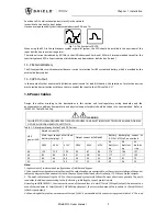
WARNING: battery hazards
SPECIAL CARE SHOULD BE TAKEN WHEN WORKING WITH THE BATTERIES ASSOCIATED WITH THIS EQUIPMENT.
When connecting the battery, the battery terminal voltage will exceed 400Vdc and is potentially lethal.
Eye protection should be worn to prevent injury from accidental electrical arcs.
Remove rings, watches and all metal objects.
Only use tools with insulated handles.
Wear rubber gloves.
If a battery leaks electrolyte, or is otherwise physically damaged, it must be replaced, stored in a container
resistant to sulfuric acid and disposed of in accordance with local regulations.
If electrolyte comes into contactor with the skin, the affected area should be washed immediately with water.
1.2 Initial Checking
Perform the following checking operations prior to the UPS installation.
1. Visually examine if there is any damage inside and outside the UPS rack and battery equipment due to the
transportation. Report any such damage to the shipper immediately.
2. Verify the product label and confirm the correctness of the equipment. The equipment label is attached on the back
of front door. The UPS model, capacity and main parameters are marked on the label.
1.3 Location
1.3.1 UPS Location
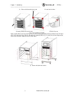
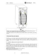
The UPS is intended for indoor installation and should be located in a cool, dry and clean environment with adequate
ventilation to keep the environmental parameters within the specified operating range (see
Table.9-2
).The Modular series
UPS uses forced convection cooling by internal fans. Cooling air enters the module through ventilation grills located at
the front part of the cabinet and exhausted through grills located in the rear part of the cabinet. Please do not block the
ventilation holes.
警告
危 险
警告
危 险
警告
危 险
Содержание M10U
Страница 1: ......
Страница 9: ......
Страница 71: ...Appendix B Power Connection of Modular System 62 Shield M10U user manual ...