UP-3301US
DIAGNOSTICS SPECIFICATIONS
– 23 –
CHAPTER 6. DIAGNOSTICS SPECIFICATIONS
1. General
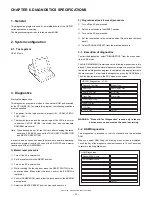
This diagnostics program is used for a simplified check of the UP-3301
series operations in servicing.
The diagnostics program is built in the standard ROM.
2. System configuration
2-1. Test system
UP-3301 only
3. Diagnostics
Starting the diagnostics
This diagnostics program is written in the external ROM and executed
by the CPU (H8/510). To operate this program, the following conditions
must be satisfied.
1
The power for the logic system is proper.(+5V, VRAM, VCKDC,
POFF, +20V)
2
The input/output pins and the internal logic of the CPU are normal.
In addition, CKDC9, MPCA8, the system bus, and the standard
ROM/RAM are normal.
Note: When booting the set for the first time after changing the touch
panel and EE-PROM, carry out the TOUCH KEY CALIBRATION
and MASTER RESETTING.
In order to add an option unit when the machine is normally operating,
perform the program reset in the case of the ER-A7RS2 and a master
reset in case of the UP-S02MB2M.
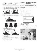
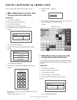
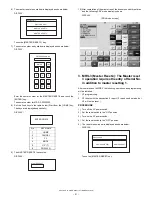
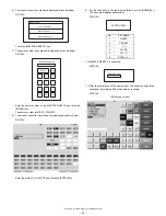
1) Master reset procedure
1
Turn off the AC power switch.
2
Set the reset switch to the RESET position.
3
Turn on the AC power switch.
4
While touching the touch panel, place the RESET SWITCH to the
normal position. (When either the touch panel or the EE-ROM is
replaced.)
5
Perform CALIBRATION, when either the touch panel or the EE-ROM
was replaced.
6
Select the MASTER RESET from the menu and execute it.
2) Program reset (service reset) procedure
1
Turn off the AC power switch.
2
Set the reset switch to the RESET position.
3
Turn on the AC power switch.
4
Set the reset switch to the normal position. (Do not press the touch
panel.)
5
Select PROGRAM RESET from the menu and execute.
3-1. Execution of diagnostics
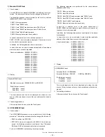
To start the diagnostics, select "DIAGNOSTICS" from the menu selec-
tion in SRV mode.
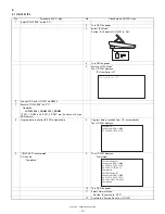
The DIAG MAIN MENU is started and the following menu screen is dis-
played. The selected individual diagnostics program is executed. When
the individual diagnostics program is completed, the display returns to
the menu screen. To terminate the diagnostics, press the CANCEL key.
Then the display returns to the SRV mode menu screen.
WARNING: "Product & Test Diagnostics" is used only in the pro-
duction process, and must not be used in servicing.
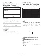
3-2. RAM Diagnostics
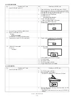
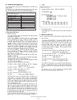
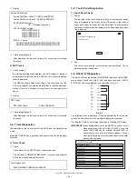
This diagnostics is intended to test the standard and the extended
RAM.
When you select RAM Diag, the following menu screen is displayed.
Touch the key of the diagnostic you want to execute. Touch Cancel key
to return to the Diag Main menu.
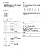
Product & Test Diag
Drawer Diag
RAM Diag
Rear Display Diag
ROM & SSP Diag
MCR Diag
Clock Diag
Printer Diag
Touch Panel Diag
Serial I/O Diag
LCD Diag
TCP/IP Diag
Cancel
UP-3301 Diagnostics V1.0A
Standard RAM Check
UP-S02MB2M Check
Cancel
RAM Diagnostics
Содержание UP-3301
Страница 91: ...UP 3301US PWB LAYOUT 89 CHAPTER 9 PWB LAYOUT 1 MAIN PWB A side ...
Страница 92: ...UP 3301US PWB LAYOUT 90 B side 8 CUSTOMER DISPLAY PWB ...
Страница 93: ...UP 3301US PWB LAYOUT 91 2 IR PWB 3 LCD PWB A Side B Side 4 INVERTER PWB A Side B Side ...
Страница 94: ...UP 3301US PWB LAYOUT 92 5 MOTHER PWB 6 N F PWB 7 TOUCH PANEL PWB ...
Страница 95: ...UP 3301US PWB LAYOUT 93 ...
Страница 111: ......


