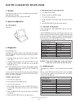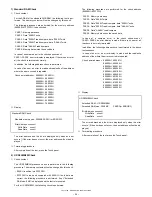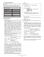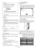
UP-3301US
DIAGNOSTICS SPECIFICATIONS
– 33 –
3-11. Drawer Diagnostics
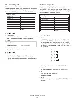
This diagnostics is used to check the drawer open and sensors.
The following menu is displayed. Press the position of the operation you
want to perform to execute individual Diag programs.
Pressing the CANCEL key returns the screen to the Diag MAIN menu.
1) Drawer 1 Check
1
Check content
The solenoid of drawer 1 is turned on, and the drawer open sensor
value is sensed at every 100ms, and the state is displayed.
2
Display
3
Terminating procedure
Press the Touch panel to terminate the check.
2) Drawer 2 Check
1
Check content
The solenoid of drawer 2 is turned on, and the drawer open sensor
value is sensed at every 100ms, and the state is displayed.
The display and the terminating procedure are the same as Drawer
1 Check.
3-12. Printer Diagnostics
I/F loopback and printing tests of the printer are performed.
The following menu appears. Press the name of the test you want to
perform to execute its Diag program. When the Diag program is termi-
nated, the screen returns to the Printer Diagnostics menu. Pressing the
CANCEL key returns to screen to the Diag Menu.
1) Loop Back Check
1
Check
A LOOPBACK test on the built-in printer (UP-T80BP) interface
(logic channel 7 of RS232) is performed and the result is displayed.
The test itself is the same as that for the RS232. The difference in
test specifications is as follows: The loopback signals are for ER-
DR, RS-CS, TXD-RXD only and the following LOOPBACK-Connec-
tors are required.
Wiring diagram of loopback connectors (UKOG-2356BHZZ)
2
Indication
The indication is the same as that for RS232 DIAGNOSTICS.
3
End
Press the PANEL to end the program.
2) Printer Print Check
1
Check
Send the signal to generate a receipt (by DIAG COMMAND) to the
UP-T80BP.
Drawer1 Check
Drawer Open Sensor
: OPEN (or CLOSE)
Drawer 1 Check
Cancel
Drawer Diagnostics
Drawer 2 Check
Loop Back Check
Printer Print Check
Cancel
Printer Diagnostics
1pin
2pin
3pin
4pin
5pin
6pin
7pin
8pin
9pin
CD
RD
SD
ER
GND
DR
RS
CS
CI
Содержание UP-3301
Страница 91: ...UP 3301US PWB LAYOUT 89 CHAPTER 9 PWB LAYOUT 1 MAIN PWB A side ...
Страница 92: ...UP 3301US PWB LAYOUT 90 B side 8 CUSTOMER DISPLAY PWB ...
Страница 93: ...UP 3301US PWB LAYOUT 91 2 IR PWB 3 LCD PWB A Side B Side 4 INVERTER PWB A Side B Side ...
Страница 94: ...UP 3301US PWB LAYOUT 92 5 MOTHER PWB 6 N F PWB 7 TOUCH PANEL PWB ...
Страница 95: ...UP 3301US PWB LAYOUT 93 ...
Страница 111: ......

