TM150
OTHERS
6 – 6
CONFIDENTIAL
DRAFT
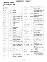
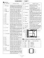
75
GPO_22
Output
VPP control for flash memory 1
76
GPIO_14
Output
PCM clock output for
Bluetooth module
77
GPIO_10
Input
USB detection
78
GPIO_12
Output
Reset output for main LCD controller/
Sub LCD driver/Power management IC
79
VMEM
Input
Memory power supply 2.7 - 3.3 V
(VMEM)
80
ADD[14]
Output
Processor address bus 14
81
GND
-
Ground
82
VCC
Input
Core power supply 1.7 - 1.9 V
(VCORE)
83
ADD[10]
Output
Processor address bus 10
84
CLKOUT
Output
13 MHz clock output for analog BB
(CLKOUT)
85
MC_DAT[3]
Input/
Output
SD interface data bus 3
86
GND
-
Ground
87
GND
-
Ground
88
GPIO_13
Input
Interrupt input from camera module
89
GPIO_7
Input
Hands free kit (earphone) detection
90
GPIO_9
Input
Manufacturer specific input from
I/O connector
91
ADD[19]
Output
Processor address bus 19
92
ADD[17]
Output
Processor address bus 17
93
ADD[18]
Output
Processor address bus 18
94
ADD[15]
Output
Processor address bus 15
95
ADD[16]
Output
Processor address bus 16
96
CSFS
Output
Control serial port framing signal
output to analog BB
97
MC_CLK
Input
SD interface clock (SD_CLK)
98
VCC
Input
Core power supply 1.7 - 1.9 V
(VCORE)
99
GPIO_11
Input
Flip switch detection
100 GPIO_8
Input
Stereo/monaural detection for
hands free kit (earphone)
101 GPIO_5
Input
SD card detection
102 GPIO_6
Input
Interrupt input from main LCD
controller
103 ADD[22]
Output
Processor address bus 22
104 ADD[21]
Output
Processor address bus 21
105 GPIO_40
Output
13 MHz clock output for main LCD
controller & Sound generator IC
106 ADD[20]
Output
Processor address bus 20
107 GND
-
Ground
108 ADD[23]
Output
Processor address bus 23
109 GND
-
Ground
110 VEXT
Input
SIM power supply 2.4 - 3.3 V
(VINT)
111 GND
-
Ground
112 GPIO_4
Output
UART_CTS for Bluetooth module
113 GPIO_2
Output
USB charge current control
114 GPIO_3
Input
UART_RTS for Bluetooth module
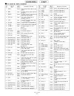
Pin
No.
Terminal
name
Input/
Output
Description of terminal
115 DATA[2]
Input/
Output
Processor data bus 2
116 DATA[0]
Input/
Output
Processor data bus 0
117 DATA[5]
Input/
Output
Processor data bus 5
118 DATA[1]
Input/
Output
Processor data bus 1
119 DATA[3]
Input/
Output
Processor data bus 3
120 VCC
Input
Core power supply 1.7 - 1.9 V
(VCORE)
121 DMINUS
Input
USB D-
122 GPIO_18
Output
JTAG TCK
123 GND
-
Ground
124 GPIO_1
Input
IrDA receive data
125 USC[5]
Input
USC pin (CTS/Ginie_TX)
126 GPIO_0
Output
IrDA transmit data
127 DATA[4]
Input/
Output
Processor data bus 4
128 VMEM
Input
SIM power supply 2.7 - 3.3 V
(VMEM)
129 GND
-
Ground
130 VCC
Input
Core power supply 1.7 - 1.9 V
(VCORE)
131 USC[6]
Input
USC pin (GPIO_31/Ginie_RX)
132 VCC
Input
Core power supply 1.7 - 1.9 V
(VCORE)
133 USC[2]
Input
USC pin (TXD)
134 USC[4]
Input
USC pin (RTS/Ginie_RX)
135 DATA[7]
Input/
Output
Processor data bus 7
136 DATA[6]
Input/
Output
Processor data bus 6
137 GND
-
Ground
138 DATA[9]
Input/
Output
Processor data bus 9
139 DATA[13]
Input/
Output
Processor data bus 13
140 NROMCS1
Output
Chip select for flash memory 1
141 GPIO_42
Output
Chip select for main LCD controller
142 CLKIN
Input
13 MHz clock input
143 VSIM
Input
SIM power supply 1.7 - 3.3 V
(VSIM)
144 GND
-
Ground
145 USC[3]
Input
Pull up to VINT
146 USC[1]
Input
USC pin (RXD)
147 GND
-
Ground
148 USC[0]
Input
USC pin (Ginie_TX)
149 DATA[10]
Input/
Output
Processor data bus 10
150 DATA[8]
Input/
Output
Processor data bus 8
151 NRD
Output
Processor read strobe
152 DATA[14]
Input/
Output
Processor data bus 14
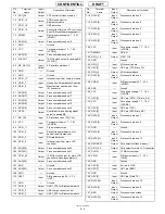
Pin
No.
Terminal
name
Input/
Output
Description of terminal
Содержание TM150
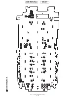
Страница 61: ...TM150 CIRCUIT DIAGRAM AND PWB LAYOUT 5 13 CONFIDENTIAL DRAFT MAIN PWB_FRONT ...
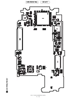
Страница 62: ...TM150 CIRCUIT DIAGRAM AND PWB LAYOUT 5 14 CONFIDENTIAL DRAFT MAIN PWB_REAR ...
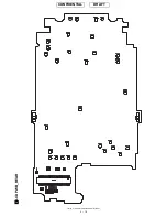
Страница 63: ...TM150 CIRCUIT DIAGRAM AND PWB LAYOUT 5 15 CONFIDENTIAL DRAFT LCD PWB_FRONT ...
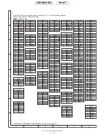
Страница 64: ...TM150 CIRCUIT DIAGRAM AND PWB LAYOUT 5 16 CONFIDENTIAL DRAFT LCD PWB_REAR ...


