TM150
ADJUSTMENTS, PERFORMANCE CHECK, AND FIRMWARE UPGRADE
2 – 20
CONFIDENTIAL
DRAFT
[Procedure]
1.
Select a channel and band. [see 4-6-3.1)]
2.
Select RX Gain using RX Gain Setting bar.
3.
Choose Sniff ON or OFF.
4.
Click "RX ON" to start receiving burst signals.
5.
From GSM tester, send burst signals in the specified channel.
(You can check each part in this state.)
6.
Click "RX OFF" to end receiving burst signals.
*
In this test, the reception timing cannot be synchronized with burst
signals from Signal Generator or GSM tester.
*
The standard RX Gain Setting is:
(Input power at the aerial connector of the handset) + (RX Gain)
= -16 dBm
Excessive Input power or RX Gain may cause damage to the handset.
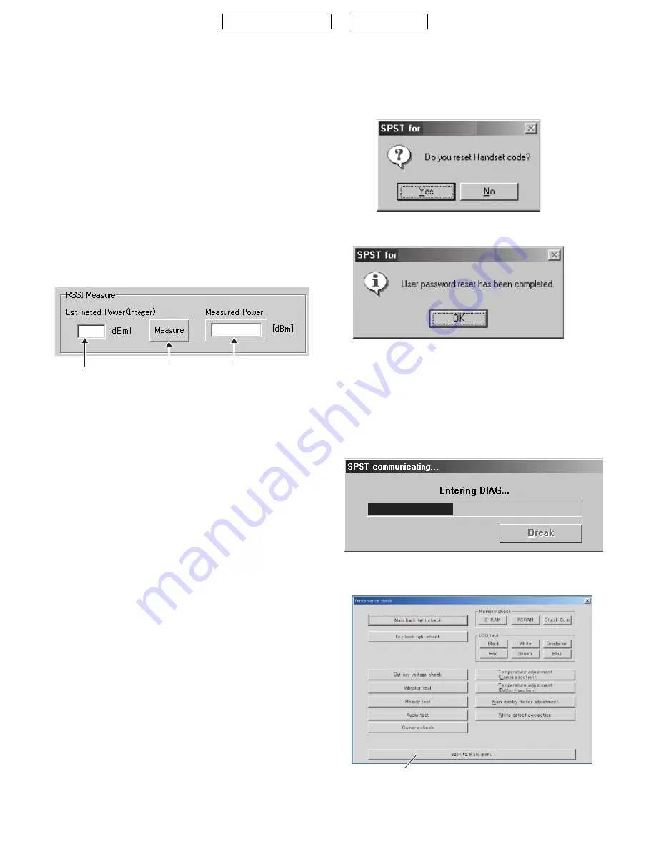
4) RSSI Measure
The handset notifies you of input power value at the aerial connector.
[Procedure]
1.
Connect the handset and GSM tester (or Signal Generator) with RF cable.
2.
Select a band and channel. [see 4-6-3. 1)]
3.
Send signals (
*
) from GSM tester.
4.
Enter the value of input power from GSM tester in integers (from -10
to -110) considering RF cable loss.
5.
Press the [Measure] button.
6.
The result appears in Measured Power box.
*
The signal type from GSM tester must be either of two:
1. Continuous sine wave (without modulation) with the frequency
as follows:
(Frequency of the measured channel) + 67.708kHz.
(Ex. channel: GSM 37ch
3
the result: 942.467708 MHz)
Power: -110 to -10 dBm
2. BCCH signal of the measured channel
Power: -110 to -10 dBm
Result
When the handset is properly calibrated, the error between "Esti-
mated Power" and "Measured Power" is less than 3dB.
4-6-4. Termination
Turn off the handset to ensure proper operations.
4-6-5. Trouble information
When switching DCS and PCS, change the channel number as well. Or
the band does not change properly.
Example: If you change DCS 512 CH to PCS 512 CH, the band
remains DCS.
4-7. Password reset
SPST resets the password (handset code is set to “0000”).
<Operation>
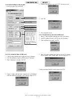
1) Set the COM port on the SPST initial screen and click “User Pass-
word Reset”. Click “Yes” to reset. Click “No” to exit.
2) When completed, the following appears.
4-8. Performance check and adjustment
With this function, SPST checks the performance of the handset and
makes adjustments.
<Operation>
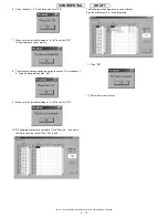
1) Set the COM port on the SPST initial screen and click "Performance
check and adjustment". The following dialog box appears while pro-
cessing.
2) When completed, the following is displayed. Click "Back to main
menu" to exit.
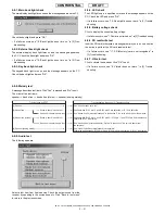
Estimated Power
Input box
(Integeronly)
Measure button
Measured power box
TM150
TM150
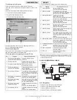
The functions of each button are described below.
Содержание TM150
Страница 61: ...TM150 CIRCUIT DIAGRAM AND PWB LAYOUT 5 13 CONFIDENTIAL DRAFT MAIN PWB_FRONT ...
Страница 62: ...TM150 CIRCUIT DIAGRAM AND PWB LAYOUT 5 14 CONFIDENTIAL DRAFT MAIN PWB_REAR ...
Страница 63: ...TM150 CIRCUIT DIAGRAM AND PWB LAYOUT 5 15 CONFIDENTIAL DRAFT LCD PWB_FRONT ...
Страница 64: ...TM150 CIRCUIT DIAGRAM AND PWB LAYOUT 5 16 CONFIDENTIAL DRAFT LCD PWB_REAR ...


