DX-SX1H
– 43 –
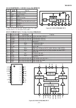
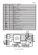
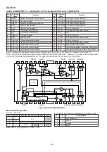
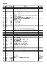
IC102 VH+-1: DC/DC Converter (BP5220)
Pin
No.
Terminal
Name
Function
1
FB
Feedback terminal
2
VOUT
Output terminal
3
GND
GND
4
CTL
ON, OFF terminal
5*
N.C.
Not used
6*
ADJ
Output voltage fine adjustment terminal
7*
N.C.
Not used
8*
—
Cut pin
9
VIN
Input terminal
In this unit, the terminal with asterisk mark (*) is (open)
terminal which is not connected to the outside.
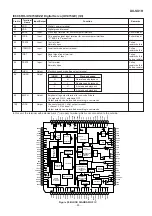
9
VIN
7
N.C.
N.C.
N.C.
5
N.C.
4
CTL
3
GND
2
VOUT
1
FB
6
ADJ
POWER
CIRCUIT
DRIVING CIRCUIT
CONTROL CIRCUIT
Figure 43-1 BLOCK DIAGRAM OF IC
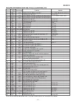
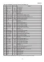
1
RSTN
Input terminal with pull-up
System reset input (Reset at L)
2
ADRS1
Input terminal with pull-up
Chip address set terminal 1
3
ADRS2
Input terminal with pull-up
Chip address set terminal 2
4
DVDD
—
Digital VDD
5
LOUT
Output
L channel audio output
6
LIN
Input
L channel audio input
7
AVDD
—
Analog VDD
8
VRL
Output
Capacity connecting terminal for L channel reference voltage (VDD/2)
9
VRR
Output
Capacity connecting terminal for R channel reference voltage (VDD/2)
10
AVSS
—
Analog VSS
11
RIN
Input
R channel audio input
12
ROUT
Output
R channel audio output
13
DVSS
—
Digital VSS
14
MLEN
Input terminal with pull-up
Microcomputer latch enable input
15
MCK
Input terminal with pull-up
Microcomputer clock input
16
MDT
Input terminal with pull-up
Microcomputer data
Pin No. Terminal Name
Input/Output
Function
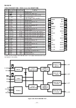
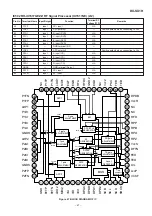
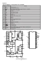
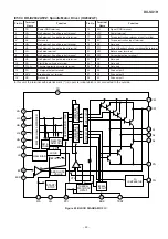
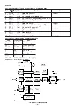
IC301 VHiSM6451AV-1: Volume Control (SM6451AV)
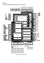
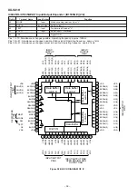
Figure 43-2 BLOCK DIAGRAM OF IC
RSTN
ADRS1
ADRS2
DVDD
LOUT
LIN
AVDD
VRL
MDT
MCK
MLEN
DVSS
ROUT
RIN
AVSS
VRR
1
2
3
4
5
6
7
8
16
15
14
13
12
11
10
9
5
LOUT
8
VRL
7
AVDD
10
AVSS
9
VRR
12
11
ROUT
RIN
13
DVSS
4
DVDD
3
ADRS2
2
ADRS1
1
RSTN
16
MDT
15
MCK
14
MLEN
6
LIN
I/F CONTROL
REFERENCE
VOLTAGE CIRCUIT
ATTENUATION
CONTROL
ATTENUATION
CONTROL
ATTENUATION DECODER
CHIP
ADDRESS
DECODER

