11
AK - 45
CHASSIS
So
ur
c
e
Se
le
ct
Loud-
SCART1
SCART2
SCART1
SCART2
SCART4
SCART3
MONO
De-
modulator
Headphone
Headphone
I
2
S
Sound
Processing
speaker
Sound
Processing
DAC
DAC
ADC
Loud-
DAC
DAC
ADC
Subwoofer
SCART
DSP
Input
Select
Pre-
processing
SCART
Output
Select
Prescale
Prescale
I
2
S1
I
2
S2
Sound IF1
Sound IF2
speaker
• Low power consumption
• Short-circuit resistant
• High performance
• high signal-to-noise ratio
• High slew rate
• Low distortion
• Large output voltage swing.
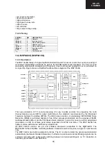
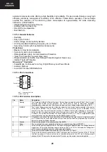
13.2.3.Pinning
SYMBOL PIN
DESCRIPTION
OUTA 1
Output
A
INA(neg)
2
Inverting input A
INA(pos)
3
Non-inverting input A
V
SS
4
Negative
supply
INB(pos)
5
Non-inverting input B
INB(neg)
6
Inverting input B
OUTB 7
Output
B
V
DD
8
Positive
supply
13.3.MSP34X0G (MSP3410G)
13.3.1.Description
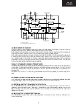
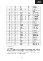
The MSP 34x0G family of single-chip Multi standard Sound Processors covers the sound processing of
all analog TV-Standards worldwide, as well as the NICAM digital sound standards. The full TV sound
processing, starting with analog sound IF signal-in, down to processed analog AF-out, is performed on
a single chip. Figure shows a simplified functional block diagram of the MSP 34x0G.
evaluated internally with subsequent switching between mono/stereo/bilingual; no I
2
C interaction is
necessary (Automatic Sound Selection).
This new generation of TV sound processing ICs now includes versions for processing the multi
channel television sound (MTS) signal conforming to the standard recommended by the Broadcast
Television Systems Committee (BTSC). The DBX noise reduction, or alternatively, MICRONAS Noise
Reduction (MNR) is performed alignment free. Other processed standards are the Japanese FM-FM
multiplex standard (EIA-J) and the FM Stereo Radio standard. Current ICs have to perform adjustment
procedures in order to achieve good stereo separation for BTSC and EIA-J. The MSP 34x0G has
optimum stereo performance without any adjustments.
All MSP 34x0G versions are pin and software downward compatible to the MSP34x0D. The
MSP34x0G further simplifies controlling software. Standard selection requires a single I
2
C transmission
only.
The MSP 34x0G has built-in automatic functions: The IC is able to detect the actual sound standard
automatically (Automatic Standard Detection). Furthermore, pilot levels and identification signals can be
Содержание C-2890EES
Страница 7: ...7 C 2890EES CHASSIS LAYOUT Mother Unit CRT Unit Control Panel Unit ...
Страница 69: ...53 AK 45 CHASSIS 14 6 GEOMETRY ADJUSTMENT 4 3 FORMATS 4 3 MODE 16 9 MODE ...
Страница 70: ...54 AK 45 CHASSIS 16 9 FORMATS AUTO MODE ...
Страница 71: ...55 AK 45 CHASSIS REGULAR MODE ...
Страница 72: ...56 AK 45 CHASSIS ZOOM 14 9 MODE ...
Страница 73: ...57 AK 45 CHASSIS ZOOM 16 9 MODE ...
Страница 74: ...58 AK 45 CHASSIS SUBTITLE ZOOM MODE ...
Страница 75: ...59 AK 45 CHASSIS FULL MODE ...
Страница 76: ...60 AK 45 CHASSIS PANORAMIC MODE ...
Страница 79: ...63 AK 45 CHASSIS 8 9 10 11 12 13 14 I H G F E D C B A Page 62 16 1 Schematic Diagram of Video IF Circuit ...
Страница 80: ...64 AK 45 CHASSIS 16 2 Schematic Diagram of µ Controller Circuit 1 I H G F E D C B A 2 3 4 5 6 7 ...
Страница 82: ...66 AK 45 CHASSIS 1 I H G F E D C B A 2 3 4 5 6 7 Page 67 16 5 Schematic Diagram of SMPS Circuit ...
Страница 83: ...67 AK 45 CHASSIS 8 9 10 11 12 13 14 I H G F E D C B A Page 66 16 5 Schematic Diagram of SMPS Circuit ...
Страница 84: ...68 AK 45 CHASSIS 1 I H G F E D C B A 2 3 4 5 6 7 Page 69 16 6 Schematic Diagram of Sound Circuit ...
Страница 85: ...69 AK 45 CHASSIS 8 9 10 11 12 13 14 I H G F E D C B A Page 68 16 6 Schematic Diagram of Sound Circuit ...
Страница 86: ...70 AK 45 CHASSIS 1 I H G F E D C B A 2 3 4 5 6 7 16 7 Schematic Diagram of CRT Socket Circuit ...
Страница 87: ...71 AK 45 CHASSIS 8 9 10 11 12 13 14 I H G F E D C B A 16 8 Schematic Diagrams of Control Panel Unit ...
Страница 88: ...72 AK 45 CHASSIS 1 I H G F E D C B A 2 3 4 5 6 7 16 9 Schematic Diagram of Remote Control Circuit ...
Страница 91: ...75 AK 45 CHASSIS Notes ...

