25
AK - 45
CHASSIS
WDR
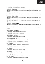
The amplitude of R of RGB output can be adjusted with the drive parameter WDR.
WDG
The amplitude of G of RGB output can be adjusted with the drive parameter WDG.
WDB
The amplitude of B of RGB output can be adjusted with the drive parameter WDB.
CR
The DC offset values of R of RGB output can be adjusted with the cutoff parameter CR.
CG
The DC offset values of G of RGB output can be adjusted with the cutoff parameter CG.
CB
The DC offset values of B of RGB output can be adjusted with the cutoff parameter CB.
COR coring level
The amplitude of the correction signal is adjustable. Small noise amplitudes in the correction signal are
suppressed by an adjustable coring circuit.
REGULAR VERT_POS (Regular mode Vertical Position)
Enter a PAL B/G circle test pattern via RF. Change Vertical Position till the test pattern is vertically
centered. Horizontal line at the center pattern is in equal distance both to upper and lower side of the
picture tube. Check and readjust Vertical Position item if the adjustment becomes improper after some
other geometric adjustments are done.
It’s used to adjust the vertical position of regular mode.
REGULAR VERT_AMPL (Regular mode Vertical Amplitude)
It’s used to adjust the vertical amplitude of regular mode.
REGULAR VERT_SCOR (Regular mode Vertical S-Correction)
It’s used to adjust the vertical s-correction of regular mode.
REGULAR VERT_SSYM(Regular mode Vertical S Symmetry)
It’s used to adjust the vertical s-symmetry of regular mode.
REGULAR TRAPEZE (Regular mode Trapeze)
Change Trapezium by pressing Left/Right buttons till vertical lines, especially lines at the sides of the
picture frame became parallel to the both sides of picture tube as close as possible. Check and readjust
TRPEZ item if the adjustment becomes improper after some other geometric adjustments are done.
It’s used to adjust the trapeze of regular mode.
REGULAR CUSHION (Regular mode Cushion)
It’s used to adjust the cushion of regular mode.
REGULAR HOR_COR_SYM (Regular mode Horizontal Corner Symmetry)
It’s used to adjust the horizontal corners symmetry of regular mode.
REGULAR HOR_CORNER (Regular mode Horizontal Corner)
It’s used to adjust the horizontal corners of regular mode.
REGULAR HORZ_POS (Regular mode Horizontal Position)
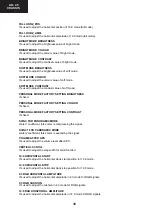
Enter a PAL B/G circle test pattern via RF. Change Horizontal Position until the picture is horizontally
centered. Check and readjust Horizontal Position item if the adjustment becomes improper after some
other geometric adjustments are done.
It’s used to adjust the horizontal position of regular mode.
REGULAR HORZ_AMPL (Regular mode Horizontal Amplitude)
It’s used to adjust the horizontal amplitude of regular mode.
Содержание C-2890EES
Страница 7: ...7 C 2890EES CHASSIS LAYOUT Mother Unit CRT Unit Control Panel Unit ...
Страница 69: ...53 AK 45 CHASSIS 14 6 GEOMETRY ADJUSTMENT 4 3 FORMATS 4 3 MODE 16 9 MODE ...
Страница 70: ...54 AK 45 CHASSIS 16 9 FORMATS AUTO MODE ...
Страница 71: ...55 AK 45 CHASSIS REGULAR MODE ...
Страница 72: ...56 AK 45 CHASSIS ZOOM 14 9 MODE ...
Страница 73: ...57 AK 45 CHASSIS ZOOM 16 9 MODE ...
Страница 74: ...58 AK 45 CHASSIS SUBTITLE ZOOM MODE ...
Страница 75: ...59 AK 45 CHASSIS FULL MODE ...
Страница 76: ...60 AK 45 CHASSIS PANORAMIC MODE ...
Страница 79: ...63 AK 45 CHASSIS 8 9 10 11 12 13 14 I H G F E D C B A Page 62 16 1 Schematic Diagram of Video IF Circuit ...
Страница 80: ...64 AK 45 CHASSIS 16 2 Schematic Diagram of µ Controller Circuit 1 I H G F E D C B A 2 3 4 5 6 7 ...
Страница 82: ...66 AK 45 CHASSIS 1 I H G F E D C B A 2 3 4 5 6 7 Page 67 16 5 Schematic Diagram of SMPS Circuit ...
Страница 83: ...67 AK 45 CHASSIS 8 9 10 11 12 13 14 I H G F E D C B A Page 66 16 5 Schematic Diagram of SMPS Circuit ...
Страница 84: ...68 AK 45 CHASSIS 1 I H G F E D C B A 2 3 4 5 6 7 Page 69 16 6 Schematic Diagram of Sound Circuit ...
Страница 85: ...69 AK 45 CHASSIS 8 9 10 11 12 13 14 I H G F E D C B A Page 68 16 6 Schematic Diagram of Sound Circuit ...
Страница 86: ...70 AK 45 CHASSIS 1 I H G F E D C B A 2 3 4 5 6 7 16 7 Schematic Diagram of CRT Socket Circuit ...
Страница 87: ...71 AK 45 CHASSIS 8 9 10 11 12 13 14 I H G F E D C B A 16 8 Schematic Diagrams of Control Panel Unit ...
Страница 88: ...72 AK 45 CHASSIS 1 I H G F E D C B A 2 3 4 5 6 7 16 9 Schematic Diagram of Remote Control Circuit ...
Страница 91: ...75 AK 45 CHASSIS Notes ...

