- 13 -
115.6001.10
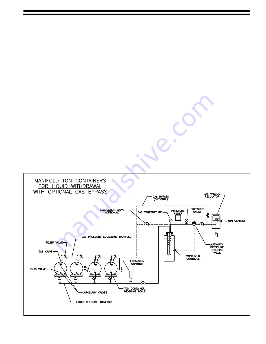
Figure 7 - Typical Manifold Piping
2.3
Piping (See Figures 6 and 7 and Bulletins 115.3002 and 115.3003)
NOTES:
All chemical carrying pipes and fittings must be Schedule 80 seamless steel or forged steel
conforming to ASTM A-105 and A-106, Grade B.
All piping, valves and fittings must be thoroughly cleaned of all oils and foreign matter prior to assembly in
accordance with Chlorine Institute Pamphlet #6. Failure to do so may result in a combustible reaction. Steam
is the best method of cleaning, but chlorinated solvents are also acceptable if used in conjunction with the
manufacturer’s safety recommendations.
Prior to assembly, threads on all chemical carrying pipes and fittings should be wrapped with Teflon tape.
Alternately, a mixture of litharge and glycerin may be used on threads. However, if used, the pipe cannot be
taken apart once set.
Connect the chemical gas, liquid lines, and water lines as shown in Figure 6. Plumbing must be in accordance
with local codes. When installing the nipples, tees and 1" ammonia unions into the inlet and outlet ports of the
chemical vaporizing chamber, be sure the unions are positioned beyond the vaporizer top plate to permit removal
of the vaporizer chamber. Make sure the correct fittings on the chamber flange are used for the inlet and outlet
piping or improper operation will result (See Figure 4). The flange is marked accordingly.
2.3.1
Gas Line Connections
a.
Install the pressure relief valve as shown in Bulletin 115.6020 and Figure 6. The relief valve must
be installed without a shutoff valve between it and the vaporizer gas outlet. Install a manual
valve in parallel with the pressure relief valve. This valve will normally be in the closed position.
It may be opened as a MANUAL vent valve ONLY. Route a 1" vent pipe from the pressure relief
valve to a point outdoors where gas discharge can be tolerated. Position the end of the pipe
downward so it will not collect foreign matter or water.
Содержание VAX4600 Series
Страница 4: ...115 6001 10 4...
Страница 6: ...115 6001 10 6 Figure 1 Vaporizer Flow Diagram Figure 2 Chemical Boiling Points at System Pressure...
Страница 9: ...9 115 6001 10 Figure 4 Cabinet Dimensions Utility Connection Locations...
Страница 12: ...115 6001 10 12 Figure 6 Vaporizer Piping Connections...
Страница 17: ...17 115 6001 10 Figure 8 Chlorine and Sulfur Dioxide Vaporizer Components...
Страница 24: ...115 6001 10 24 Figure 10 Replacing Heater Element...
Страница 26: ...115 6001 10 26...
Страница 27: ...27 115 6001 10...


