26
CamCor CT and PRO Series Hardware Manual
Section 4
26
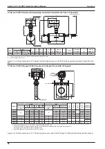
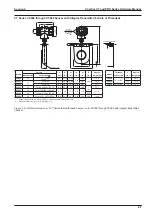
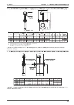
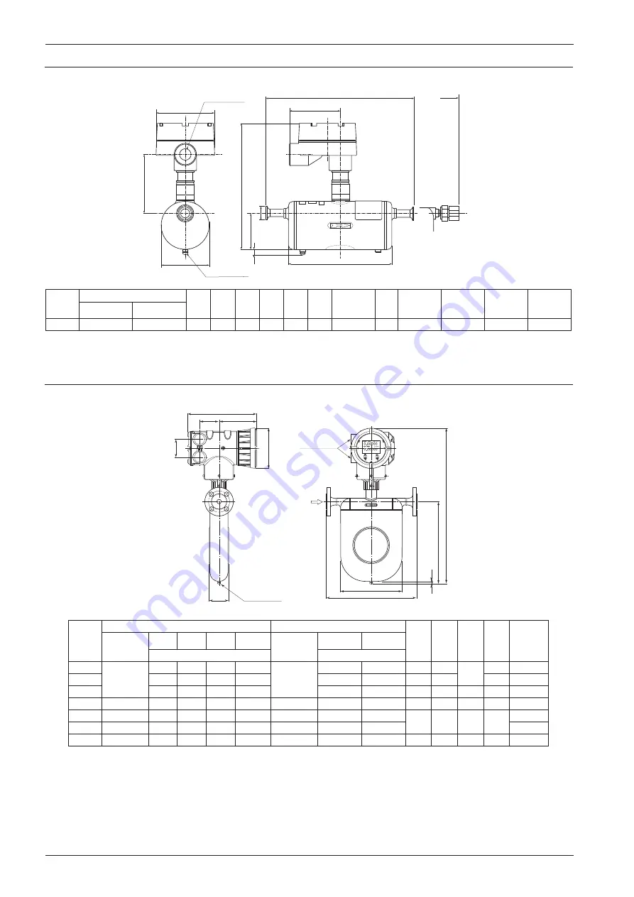
CT Series CC003 Sensor with Separately-mounted Transmitter (Ferrule or Threaded)
L
A
W
98
H
109
h1
10
Ground screw
L
φ
D
Conduit connection
3/4-14 FNPT
(M25)
3.86
4.21
4.29
0.39
Threaded connection
Model
Ferrule
L
(in.)
H
(in.)
h1
(in.)
A
(in.)
W
(in.)
D
(in.)
Approx.
Weight (lb)
Model
Threaded
Connection
L
(in.)
Approx.
Weight (lb)
Nominal size Connection
CC003
10
Ferrule 10A
10.49
9.06
2.64
3.51
7.56
1.34
9.92
CC003
1/2-14 FNPT
13.1
9.92
3. Conduit connections are 3/4-14 FNPT for CSA units and M25 for ATEX units.
2. Process connection: A = mm
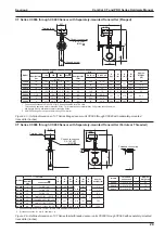
Figure 4.3—Outline dimensions of CT Series ferrule/threaded sensor unit CC003 with separately-mounted transmitter (inch-
es)
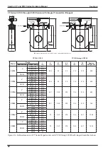
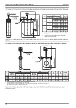
CT Series CC006 through CC080 Sensor with Integral Transmitter (Flanged)
A
W
L
5.28
h1
0.39
H
Ground screw
Conduit
connections
3/4-14 FNPT
(M25)
9.06
2.52
5.0
2.36
Flow direction
Model
ASME
DIN
H
(in.)
h1
(in.)
A
(in.)
W
(in.)
Approx.
Weight (lb)
Nominal size
(in.)
150
300
600
900
Nominal size
(DN)
PN 10, 16
PN 25, 40
L (in.)
L
CC006
1/2
10.6
10.9
11.4
12.1
15
9.49
9.72
16.7
7.09
2.09
5.83
15.4
CC010
11.1
11.5
11.9
12.6
10.1
10.3
18.2
8.58
6.42
17.2
CC015
12.8
13.1
13.7
14.3
11.8
12
20.2
10.6
2.56
8.07
19.4
CC025
1
16.2
16.7
17.2
18.1
25
14.8
15
22.8
13
3.27
10.3
29.3
CC040
1-1/2
21.5
22
22.6
23.7
40
20
20.2
28
17.8
4.76
15.2
50.7
CC050
2
21.7
22.2
22.9
25.2
50
20.2
20.4
50.7
CC080
3
27.5
28.2
29
30.6
80
25.9
26.6
34.6
23.7
6.85
20.1
125.7
1. Conduit connections are 3/4-14 FNPT for CSA units and M25 for ATEX units.
• This table only applies to meter material SUS316L. For information about material Alloy C22, please consult Cameron.
• DIN flanges are only available for meter material SUS316L.
2. ASME 900 flanges are only available in Alloy C22 material.
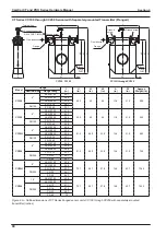
Figure 4.4—Outline dimensions of CT Series flanged sensor units CC006 through CC080 with integral transmitter (inches)
Содержание CamCor CC001
Страница 14: ...14 CamCor CT and PRO Series Hardware Manual Section 3 This page is left blank intentionally ...
Страница 24: ...24 CamCor CT and PRO Series Hardware Manual Section 3 This page is left blank intentionally ...
Страница 38: ...38 CamCor CT and PRO Series Hardware Manual Section 4 38 This page is left blank intentionally ...
Страница 54: ...54 CamCor CT and PRO Series Hardware Manual Section 5 This page is left blank intentionally ...
Страница 62: ...62 CamCor CT and PRO Series Hardware Manual Section 7 This page is left blank intentionally ...
Страница 126: ...A 10 CamCor CT and PRO Series Hardware Manual Appendix A This page is left blank intentionally ...


