11
10/06/11 Revision 1.1
4.0
Installation
4.1
BBS Components:
TABLE 1
Picture
Part Number and Description
Qty.
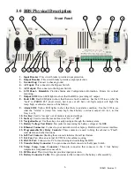
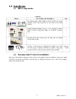
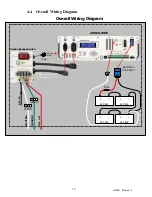
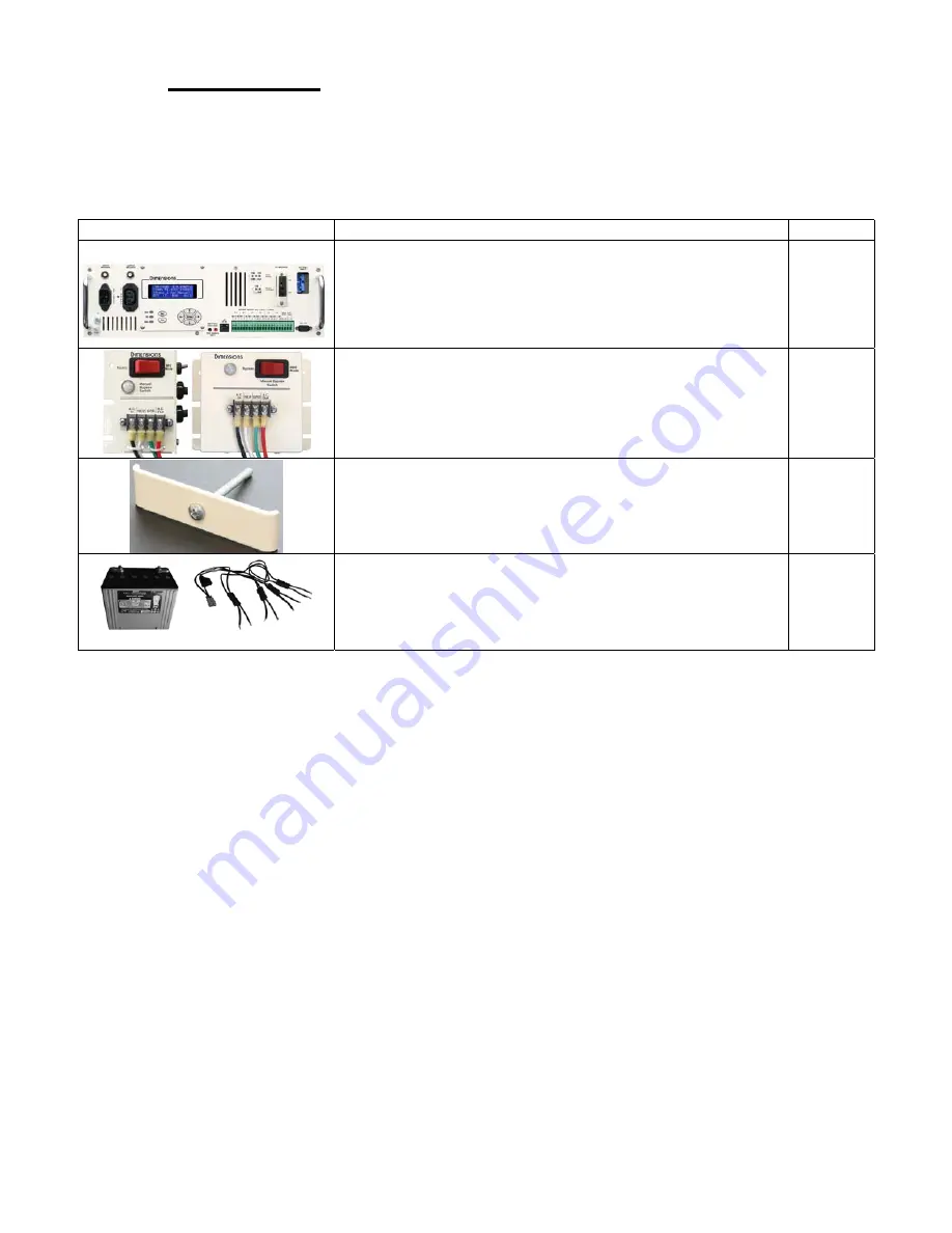
The BBS modules 48M18-WBE and 24J11-WBE have all the
interface cables and connectors on the front of the BBS
module.
1
Combined Manual Bypass Switch – 30A Automatic Transfer
Relay 511020-1 (open back panel) or 511020-2 (enclosed
case).
1
Use this Cable Stay to keep your AC Input and AC Output
cords locked in place.
1
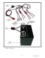
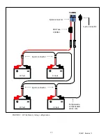
12 VDC, 79 AH Group 24 AGM batteries 390003 or 12 VDC
105 AH group 31 batteries 390006 are available. One quick
connector battery cable assembly included with each BBS.
4 Batt’s
1 Cable
4.2
Recommended Tools for Installation:
Butt type and insulated connectors, drill, crimpers (for insulated and non-insulated connectors), digital
volt meter with probes (true RMS), electrical tape, #2 Phillips screwdriver, wire cutters, wire strippers,
cable ties, and tape measure.

