6
10/06/11 Revision 1.1
3.0
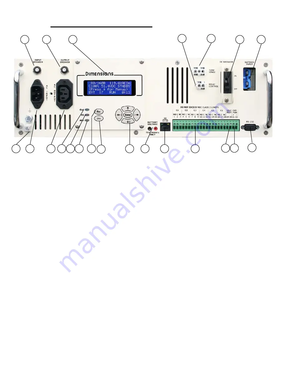
BBS Physical Description
1.
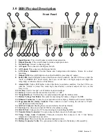
Input Breaker:
This circuit breaker provides input protection.
2.
Output Breaker:
This circuit breaker provides output protection.
3.
Ground Lug:
Connect to chassis ground.
4.
AC Input:
This connects to the Bypass Switch.
5.
AC Output:
This connects to the Bypass Switch.
6.
LCD Panel - Rotatable:
Provides Status and Configuration information. Rotate for vertical
mounting.
7.
Output LED:
Green LED lights to show that the BBS is providing AC output.
8.
Fault LED:
Red LED lights to show that there is a fault condition. See the LCD to see what the
“fault” is (PROBE FLT, short circuit, batt. Low cut off, batt. volt. high, output volt. high, bbs
temp. high, overload excessive or bbs failure).
9.
Alarm LED:
Yellow LED lights to show that there is an alarm condition. See the LCD to see
what the “Alarm” is (temp. low, temp. high, check battery, overload, output volt. low, ac line
freq. L or h).
10.
Esc Key:
Used to “escape” out of menu screens and settings.
11.
Inv Key:
Used to turn the inverter function “On” or “Off”.
12.
Navigation Keys:
Use these keys to easily navigate through the menu system.
13.
Battery Voltage Test Points:
Test jacks for measuring the battery voltage at the BBS.
14.
Ethernet Connector:
Connect to your network switch or laptop. Built-in web browser interface.
15.
Programmable Dry Relay Contacts:
These contacts are used to bring the cabinet to “Flash”,
send alarms, and other functions.
16.
Self Test Contacts:
Shorting these contacts initiates the self test feature.
17.
Ext. Fan:
Can drive an external 24 VDC fan for cabinet cooling.
18.
RS-232 Port:
Connects to a PC for monitoring and controlling the BBS.
19.
Transfer Relay Connector:
Two-pin connector that connects to the Bypass Switch.
20.
Temp. Comp. Sense Connector:
Three-pin connector that connects to the 9 foot battery
temperature compensation sense cable.
21.
DC Breaker:
This circuit breaker provides input protection.
22.
Battery Connector Cable:
Two-pin connector that connects to the battery cable assembly.
Front Panel
15
1
14
2
4
5
13
12
11
7
8
9
10
16 17
19
18
20
21
6
22
3

