18
10/06/11 Revision 1.1
4.5.4
Dry-Relay Contact Wiring
Risk of electrocution may exist when working with the dry relay contacts depending on how
your cabinet is interfaced to the BBS. Take necessary safety precautions.
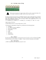
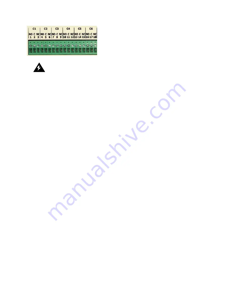
Dry relay connections provide a means for the BBS to bring the cabinet to flash under desired conditions
(For example, during a low battery condition). These contacts also allow the controller to indicate various
alarm, fault or BBS status conditions. There are 6 relays which are user programmable (C1-C6). The
factory default positions of the relays are:
| C1 – On Battery | C2 – On Battery | C3 – Low Battery | C4 – Low Battery | C5 – Timer | C6 – Timer |
Contact rating is 3A/125Vac
Terminal blocks accept 12 to 22 awg wiring, torque is 7 in/lbs
The relays may be programmed to trigger for any combination of the following options:
•
On Battery
•
Low Battery (set point is adjustable)
•
Timer (time is adjustable)
•
Time Of Day
•
Alarm
•
Fault
•
BBS Failure
•
Disable/Enable
4.5.5
Self Test
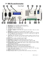
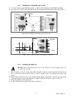
By momentarily shorting contacts 19 & 20 together (see above figure), a self test is initiated in the BBS.
The test will only occur if the BBS is in “Standby”. The test will run for the duration set in the BBS.
4.5.6
External Fan
A 24VDC cabinet fan may be connected to contacts 21 & 22.

