53
© Sealevel Systems, Inc.
SeaI/O | SL9049 11/2021
Hardware Configuration, Continued
A Hardware Reset will not reset the communication rate of Ethernet (E-series) and Wireless (W-series)
modules. Rotate the rotary switch clockwise one full revolution, and then use the MaxSSD utility to
broadcast a set baud rate command to 9600 bps and no parity.
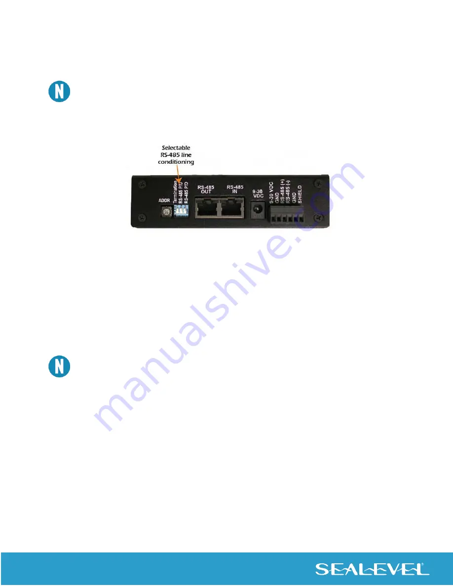
Setting Termination & Pull-Up/Pull-Down Resistors
A “stack” or “chain” of SeaI/O modules, connected via the pass
-through connectors or screw terminals on the
left side of the enclosure, communicates via an RS-485 bus, which must be properly terminated to work correctly.
A set of three dipswitches is located on the left side of enclosure, next to the “ADDR” rotary switch. These
switches control line termination and the RS-485 pull-up and pull-down resistors.
The pull-up and pull-down resistors ensure that the input ports are at a known state when not being driven by
the RS-485 line. In most cases, all three of the dipswitches on each SeaI/O module should be in the down
position, except the two end modules. The first and last SeaI/O modules in the chain should have all three
dipswitches in the up (enabled) position.
Make sure that only the first and last SeaI/O modules have line termination enabled (up position).
Improper termination settings can result in invalid data or communication failures.
Configuring the “Base” SeaI/O Module
Once the SeaMAX Software Suite has been installed successfully and you have decided which address (slave
ID) method you intend to use, start by connecting the first SeaI/O module to your computer. This will be referred
to as the “base” module.
If you are chaining multiple SeaI/O modules together, only o
ne SeaI/O module in the chain can be the “base”.
All other SeaI/O modules connected to the “base” module are referred to as expansion modules. Multiple “base”
modules can be directly connected to a host computer, but expansion modules must be connected (daisy
chained) to a “base” module.


