Maintenance
9711-92 Ku-Band TXRX
18-6
-6
Below
Decks
2 Wire RS485
(Half Duplex)
5-6
7-8
9-10
18.5.
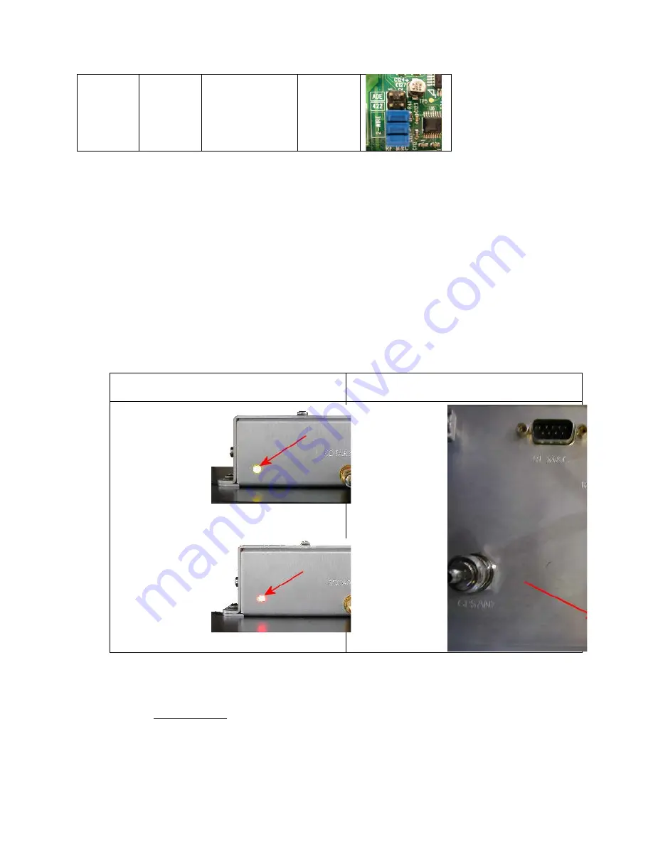
400 MHz LED indicators
For diagnostic purposes, the 400MHz FSK modem sssemblies have an LED Indicator (located to the on the bottom left
hand side of the enclosure for BDE modems and directly underneath the rotary joint port on the 09 Series PCU). By
observing the amount of amber colored flashes during power up, the modems configuration may be established. You
can also verify the communications link between above decks and below decks modems themselves. Refer to the
below list for an explanation of the different LED states.
•
Upon power up, the modems’ LED will flash amber. The number of flashes indicates the dash number
configuration of the modem. Refer to the configuration chart above for the appropriate dash
configuration for your modem assembly.
•
A flashing Red LED indicates no communication between modems (2 failed channels).
•
An LED alternating Red and Green indicates a single channel failure.
•
Solid green indicate dual channel communications lock between modems (i.e. there is enough signal
being received to establish communications).
•
•
Below Decks Modem
Assembly
•
Above Decks Modem
(Located in PCU Assembly)
•
Figure 6 LED Illuminated Green
•
•
Figure 7 LED Illuminated Red
•
18.6.
400 MHz Modem Signals
18.6.1.
Pedestal M&C
RS-422 antenna M&C signals pass from the ACU’s J4 Antenna Port, through the PED M&C port of the
400MHz base modem and are modulated and demodulated. The modulated signal(s) are then diplexed with
the RxIF signal. This modulated signal travels on the Rx IF cable, between the MUX Rack Panel and then into
400 MHz pedestal modem. The Pedestal modem then converts the RF Signal back to RS-422, before routing
to the M&C port of the PCU via an interface cable.
Содержание 9711-92
Страница 3: ......
Страница 10: ...Table of Contents x 22 2 9711 GENERAL DRAWINGS 22 1 This Page Intentionally Left Blank ...
Страница 22: ...Site Survey 9711 92 Ku Band TXRX 2 8 This Page Intentionally Left Blank ...
Страница 62: ...Basic Setup of the ACU 9711 92 Ku Band TXRX 4 4 This Page Intentionally Left Blank ...
Страница 64: ...Setup Ships Gyro Compass 9711 92 Ku Band TXRX 5 2 This Page Intentionally Left Blank ...
Страница 66: ...Setup Band Select 9711 92 Ku Band TXRX 6 2 This Page Intentionally Left Blank ...
Страница 72: ...Setup Home Flag Offset 9711 92 Ku Band TXRX 8 4 This Page Intentionally Left Blank ...
Страница 80: ...Setup Searching 9711 92 Ku Band TXRX 10 6 This Page Intentionally Left Blank ...
Страница 92: ...Setup Modem Connections Setup and Test 9711 92 Ku Band TXRX 12 8 This Page Intentionally Left Blank ...
Страница 100: ...Antenna Specific Operation 9711 92 Ku Band TXRX 15 4 This Page Intentionally Left Blank ...
Страница 104: ...Functional Testing 9711 92 Ku Band TXRX 16 4 This Page Intentionally Left Blank ...
Страница 120: ...Installation Troubleshooting 9711 92 Ku Band TXRX 17 16 This Page Intentionally Left Blank ...
Страница 142: ...Maintenance 9711 92 Ku Band TXRX 18 22 This Page Intentionally Left Blank ...
Страница 158: ...9711 92 Technical Specifications 9711 92 Ku Band TXRX 21 10 This Page Intentionally Left Blank ...
Страница 160: ...Drawings 9711 92 Ku Band TXRX 22 2 This Page Intentionally Left Blank ...
Страница 166: ......
Страница 167: ......
Страница 168: ......
Страница 191: ......
Страница 192: ......
Страница 194: ......
Страница 196: ......


