Section 06
ENGINE MANAGEMENT (DI)
Subsection 03
(COMPONENT INSPECTION AND ADJUSTMENT)
SMR2002-030 _06_03A.FM
06-03-15
Installation
For the installation, reverse the removal proce-
dure. Paying attention to the following details.
If the same injector is reinstalled, it is recommend-
ed to change the O-rings.
Insert the fuel injector in place with your hand. Do
not use any tool.
NOTE:
A thin film of injection oil may be applied
to O-ring to ease insertion in rail.
Apply Loctite 243 on rail retaining screws then torque
to 25 N•m (18 lbf•ft).
AIR/FUEL RAIL
Pressure Test
Crank or start engine
and observe fuel pressure.
If pressure is within limits, fuel and air systems are
working adequately. No subsequent tests are nec-
essary for the air/fuel system.
Remove pressure gauge and reinstall fuel hose. At
installation apply engine oil on O-ring.
If pressure is out of limits, check air/fuel rail for
leaks. If it is not leaking then replace air regulator
A higher pressure may be an indication of a
pinched or clogged air regulator outlet line.
Air Pressure Regulator Replacement
Removal
See FUEL PRESSURE REGULATOR REMOVAL
above for procedure.
Remove the fuel regulator then the air regulator.
Installation
For the installation, reverse the removal procedure
but pay attention to the following.
NOTE:
A thin film of injection oil may be applied
to O-ring to ease insertion in rail.
Apply Loctite 243 on rail retaining screws then
torque to 25 N•m (18 lbf•ft).
Air/Fuel Rail Replacement
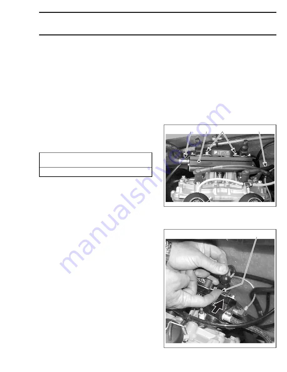
Removal
Release the fuel pressure in the system.
Disconnect air compressor supply hose from rail.
Disconnect fuel hoses (supply and return) at their
inline connectors.
Temporarily connect those hose ends together to
prevent rail draining.
Disconnect spark plug cables from spark plugs
and fuel injector wires. Cut locking ties of wiring.
Unscrew rail retaining screws.
1. Air/fuel rail
2. Air supply hose
3. Fuel supply hose
4. Retaining screws
1. Push clip toward injector to release connector
FUEL PRESSURE
(when cranking engine or when engine is running)
738 ± 14 kPa (107 ± 2 PSI)
3
1
4
2
F12R0CA
1
F12R0DA
www.SeaDooManuals.net
Содержание GTI 5558
Страница 1: ...www SeaDooManuals net ...
Страница 2: ...2002 Shop Manual Volume 1 GTI GTI LE GTX GTX RFI XP RX RX DI LRV DI www SeaDooManuals net ...
Страница 541: ...2002 GTI MODEL www SeaDooManuals net ...
Страница 542: ...SMR2002 051_16_00A FM 2002 GTI MODEL F17Z01 www SeaDooManuals net ...
Страница 543: ...2002 GTI LE MODEL www SeaDooManuals net ...
Страница 544: ...SMR2002 051_16_00A FM 2002 GTI LE MODEL F11Z02 www SeaDooManuals net ...
Страница 545: ...2002 GTX MODEL www SeaDooManuals net ...
Страница 546: ...SMR2002 051_16_00A FM 2002 GTX MODEL F07Z01 www SeaDooManuals net ...
Страница 547: ...2002 GTX RFI MODEL www SeaDooManuals net ...
Страница 548: ...SMR2002 051_16_00A FM 2002 GTX RFI MODEL F15Z04 www SeaDooManuals net ...
Страница 549: ...2002 XP MODEL www SeaDooManuals net ...
Страница 550: ...SMR2002 051_16_00A FM 2002 XP MODEL F08Z02 www SeaDooManuals net ...
Страница 551: ...2002 RX MODEL www SeaDooManuals net ...
Страница 552: ...SMR2002 051_16_00A FM 2002 RX MODEL F16Z03 www SeaDooManuals net ...
Страница 553: ...2002 RX DI MODEL www SeaDooManuals net ...
Страница 554: ...SMR2002 051_16_00A FM 2002 RX DI MODEL F16Z04 www SeaDooManuals net ...
Страница 555: ...2002 LRV DI MODEL www SeaDooManuals net ...
Страница 557: ...www SeaDooManuals net ...


