PAGE 66
8.0 TROUBLE SHOOTING GUIDE
8.1 ELECTRICAL TROUBLE SHOOTING - MOTOR
CAUTION: ALL ELECTRICAL WORK PERFORMED ON THE FI-8510-20M IRONWORKER
SHOULD BE PERFORMED BY A QUALIFIED ELECTRICIAN.
A.
MOTOR WILL NOT RUN:
1.
Check the selector switch. The machine will not start unless the selector switch is in the START
position.
2.
Check the disconnect switch. Make sure that it is in the ON position.
3.
Check the emergency stop buttons. A defective or stuck emergency stop button will not allow the
machine to be powered. To check the emergency stop buttons, place a jumper wire between
terminals x1 and 1. Turn the machine on. If the machine runs, turn the power off, remove the
jumper and repair or replace the emergency stop buttons.
DO NOT OPERATE THIS MACHINE WITH THE EMERGENCY STOP BUTTONS
BYPASSED!!
4.
Check to be sure that the plant voltage and phase correspond to the machine voltage and phase.
5.
Check the line wiring connections at the starter. (For the wiring diagram, SEE FIGURE 4 ON
PAGE 15.)
6.
Check the line voltage at the starter. If the correct line voltage is present at the starter, either the
starter or the motor is defective. Contact your local dealer or the factory.
B.
THE MOTOR RUNS BUT THE MACHINE WILL NOT CYCLE WHEN DEPRESSING THE
FOOT PEDAL:
1.
Check the selector switch. The machine will not move unless the selector switch is in either the
PUNCH or the SHEAR position.
2.
Check the motor rotation. It should be counterclockwise when viewed from the shaft end of the
motor.
3.
Check the stroke control adjustment and make sure that only one limit switch is in contact with
the metering boss. If both limit switches are in contact with the metering boss, the machine will
not move. Loosen the stroke control handles and move the limit switches. Try the machine again.
4.
Check the run/jog switch. The foot pedal will not operate the machine when this switch is in the
JOG position.
Содержание FI-8510-20M
Страница 10: ...PAGE 9 FIGURE 1...
Страница 12: ...PAGE 11 FIGURE 2...
Страница 24: ...PAGE 21 FIGURE 6...
Страница 26: ...PAGE 23 FIGURE 7...
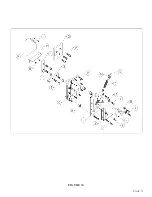
Страница 38: ...PAGE 35 FIGURE 15...
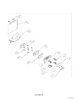
Страница 40: ...PAGE 37 FIGURE 16...
Страница 42: ...PAGE 39 FIGURE 17...
Страница 44: ...PAGE 41 11 Install the notcher table H and adjust the guard down to the proper height FIGURE 18...
Страница 48: ...PAGE 45 FIGURE 20...
Страница 50: ...PAGE 47 FIGURE 21...
Страница 52: ...PAGE 49 FIGURE 22...
Страница 56: ...PAGE 53 FIGURE 24...
Страница 58: ...PAGE 55 FIGURE 25...
Страница 62: ...PAGE 59 FIGURE 26...
Страница 64: ...PAGE 61 FIGURE 27...
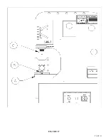
Страница 68: ...PAGE 65 FIGURE 29...
Страница 74: ...PAGE 71 FIGURE 30...
Страница 76: ...PAGE 73 FIGURE 31...
Страница 80: ...PAGE 77 FIGURE 33...
Страница 82: ...PAGE 79 FIGURE 34...
Страница 84: ...PAGE 81 FIGURE 35...
Страница 88: ...PAGE 85 FIGURE 37...
Страница 90: ...PAGE 87 FIGURE 38...
Страница 92: ...PAGE 89 FIGURE 39...
Страница 94: ...PAGE 91 FIGURE 40...
Страница 96: ...PAGE 93 FIGURE 41...
Страница 100: ...PAGE 97 FIGURE 43 SERIAL S 4481 UP...

