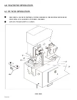
Page 38
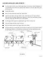
The rod shear cavity is designed to shear up to 1-1/2 inch (38mm) round and 1-1/4 inch (31mm) square
rods. To prevent kick-up of the material, adjust the hold-down device to within 1/16 inch (1.5mm) of the
material. For best results, always feed the material at a true horizontal plane to the blades.
6.5 ROD SHEAR OPERATION
NEVER allow any portion of your body to extend beyond any of the guards or hold-down devices
on this ironworker.
The rod shear is operated with the selector switch in the SHEAR position. Lubricate the blades every 10
to 15 cuts. Special blades are available. For prices, contact your local dealer or the factory.
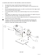
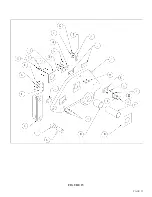
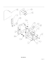
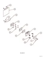
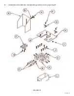
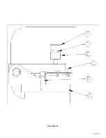
For parts identification, SEE FIGURE 17 ON THE FOLLOWING PAGE.
1.
Remove the handle (I) holding the guard hold-down device (D) to the machine.
2.
Remove the bolts (H) holding the stationary blade holder (C) and the blade.
3.
After removing the holder, back the set screw adjustment bolts (G) off until they retract into the
holder.
4.
It may be necessary to power the machine and jog the tooling beam to a position where the moving
blade (A) can be removed.
5.
After jogging the machine, turn the power off and remove the moving blade.
6.
At this point, the blade may be sharpened or new blades installed.
7.
8.
Install the moving blade (A) on the tooling arm.
9.
Place the stationary blade (B) and holder (C) on the machine and start the mounting bolts.
DO NOT TIGHTEN.
10.
With steady hand pressure, hold the stationary blade against the moving blade and adjust the
adjustment screws (G) in until they contact the frame of the machine. Turn the adjustment screws
in 1/4 of a turn more after they contact the frame.
11.
A clearance of ten thousandths (.010) of an inch (.25mm) is recommended.
11. Tighten the mounting bolts (H) and mount the guard hold-down device (B).
6.5A ROD SHEAR BLADE ADJUSTMENT OR REPLACEMENT
►
NOTE: The blades are designed to fit only one way and can not be reversed.
Содержание FI-8510-20M
Страница 10: ...PAGE 9 FIGURE 1...
Страница 12: ...PAGE 11 FIGURE 2...
Страница 24: ...PAGE 21 FIGURE 6...
Страница 26: ...PAGE 23 FIGURE 7...
Страница 38: ...PAGE 35 FIGURE 15...
Страница 40: ...PAGE 37 FIGURE 16...
Страница 42: ...PAGE 39 FIGURE 17...
Страница 44: ...PAGE 41 11 Install the notcher table H and adjust the guard down to the proper height FIGURE 18...
Страница 48: ...PAGE 45 FIGURE 20...
Страница 50: ...PAGE 47 FIGURE 21...
Страница 52: ...PAGE 49 FIGURE 22...
Страница 56: ...PAGE 53 FIGURE 24...
Страница 58: ...PAGE 55 FIGURE 25...
Страница 62: ...PAGE 59 FIGURE 26...
Страница 64: ...PAGE 61 FIGURE 27...
Страница 68: ...PAGE 65 FIGURE 29...
Страница 74: ...PAGE 71 FIGURE 30...
Страница 76: ...PAGE 73 FIGURE 31...
Страница 80: ...PAGE 77 FIGURE 33...
Страница 82: ...PAGE 79 FIGURE 34...
Страница 84: ...PAGE 81 FIGURE 35...
Страница 88: ...PAGE 85 FIGURE 37...
Страница 90: ...PAGE 87 FIGURE 38...
Страница 92: ...PAGE 89 FIGURE 39...
Страница 94: ...PAGE 91 FIGURE 40...
Страница 96: ...PAGE 93 FIGURE 41...
Страница 100: ...PAGE 97 FIGURE 43 SERIAL S 4481 UP...

