PAGE 42
6.7 JOG CONTROL
On the FI-8510-20M Ironworker, a jog control is standard equipment. To utilize this feature, place the
run/jog switch in the JOG position. When the switch is in the JOG position, the foot pedal is inoperable.
When the switch is in the RUN position, the jog control is inoperable. This feature is very helpful for
setting the stroke controls precisely, to eliminate excessive travel to the workpiece and setting up the
optional tooling that is available for the punch station. The jog control is also used for many of the
maintenance and repair functions discussed in this manual.
CAUTION: WHEN THE JOG FEATURE IS USED, THE MACHINE WILL REMAIN AT
WHATEVER POINT THE JOG CONTROL IS RELEASED. WHEN THE RUN/JOG SWITCH
IS CHANGED TO THE "RUN" POSITION, THE MACHINE WILL MOVE TO WHATEVER
POSITION THE SELECTOR SWITCH IS SET IN.
7.0 OPTIONAL TOOLS
This segment will cover the optional tools that can be purchased for the FI-8510-20M, along with the
proper and safe methods to install and operate them. As with all functions of this machine, safety glasses
are required when using any of these tools.
7.1 PIPE NOTCHER
The pipe notcher is a component tool designed to saddle cut pipe and tubing for applications such as
railings. There are notchers available to notch angles in pipe and tubing, also. For prices and availability,
contact your local dealer or the factory. Two inch (2") schedule 80 is the maximum thickness of pipe that
can be cut. Lighter weight tubing may be cut, but will require different dies for best cutting results.
Separate dies are required for each size pipe being notched.
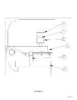
7.1A PIPE NOTCHER INSTALLATION
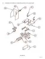
SEE FIGURE 19 ON THE FOLLOWING PAGE.
The pipe notcher installs in the punch station on this model. To install the pipe notcher, remove the
punch stripper and die holder.
1.
Before installing the pipe notcher, place the selector switch in the PUNCH position and allow the
ram to retract fully. Turn off the power to the machine.
2.
Install the punch pusher (B) and the #45 punch retaining nut (A) on the punch ram.
3.
Install the upper and lower dies and the return springs in the notcher.
4.
Bolt the riser (C) to the top notcher die.
5.
Place the notcher on the bolster (E) and line the riser (C) up to the punch pusher (B).
6.
Anchor the notcher to the bolster with the finger clamps (D) provided with the tool.
Содержание FI-8510-20M
Страница 10: ...PAGE 9 FIGURE 1...
Страница 12: ...PAGE 11 FIGURE 2...
Страница 24: ...PAGE 21 FIGURE 6...
Страница 26: ...PAGE 23 FIGURE 7...
Страница 38: ...PAGE 35 FIGURE 15...
Страница 40: ...PAGE 37 FIGURE 16...
Страница 42: ...PAGE 39 FIGURE 17...
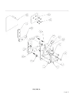
Страница 44: ...PAGE 41 11 Install the notcher table H and adjust the guard down to the proper height FIGURE 18...
Страница 48: ...PAGE 45 FIGURE 20...
Страница 50: ...PAGE 47 FIGURE 21...
Страница 52: ...PAGE 49 FIGURE 22...
Страница 56: ...PAGE 53 FIGURE 24...
Страница 58: ...PAGE 55 FIGURE 25...
Страница 62: ...PAGE 59 FIGURE 26...
Страница 64: ...PAGE 61 FIGURE 27...
Страница 68: ...PAGE 65 FIGURE 29...
Страница 74: ...PAGE 71 FIGURE 30...
Страница 76: ...PAGE 73 FIGURE 31...
Страница 80: ...PAGE 77 FIGURE 33...
Страница 82: ...PAGE 79 FIGURE 34...
Страница 84: ...PAGE 81 FIGURE 35...
Страница 88: ...PAGE 85 FIGURE 37...
Страница 90: ...PAGE 87 FIGURE 38...
Страница 92: ...PAGE 89 FIGURE 39...
Страница 94: ...PAGE 91 FIGURE 40...
Страница 96: ...PAGE 93 FIGURE 41...
Страница 100: ...PAGE 97 FIGURE 43 SERIAL S 4481 UP...


