PAGE 25
A.
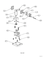
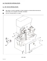
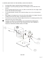
ALIGNMENT AND REMOVAL OF PUNCHES AND DIES:
WARNING: Failure to properly align punches and dies can cause serious bodily injury and/or
damage to equipment. Please read carefully and understand the following method. It will also be
helpful to refer to the safety tape provided for a visual reference. If you did not receive a safety
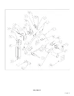
tape, please contact your dealer or the factory. For parts identification, REFER TO FIGURE 8.
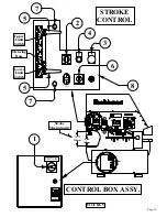
PLEASE NOTE: THERE IS AN EMERGENCY STOP PALM BUTTON ON BOTH ENDS OF
THIS MACHINE.
1.
With the machine in the PUNCH position and the ram retracted, turn the machine’s electrical
power off at the disconnect switch.
2.
Release the stripper (A) by pushing up on the right hand bolt, swinging it out of the way of the
punch ram and retaining nut.
3.
Loosen the die holder bolts (B).
4.
Remove the punch retaining nut (C) and set the punch retaining nut and punch aside.
5.
Loosen the two set screws (F) holding the die insert in the die holder. Remove the die insert and
loosen the bolt holding the die and remove the die.
NOTE: The die insert has an alignment pin in it and it must be lifted up to remove it.
6.
Place the disconnect in the ON position and the selector switch in the START position. Power the
machine by pressing the green START button.
CAUTION: IF YOU ARE USING THE OFFSET DIE HOLDER FOR FLANGED PUNCHING,
PLEASE SEE SPECIAL INSTRUCTIONS IN SECTION 7.9A BEFORE CONTINUING.
7.
Check to make sure that there are no objects (such as tools) under or on any of the moving parts.
8.
Place the selector switch in the SHEAR position and allow the ram to fully extend.
9.
Turn the machine's power OFF.
10.
Clean the die insert cavity of any foreign material.
11.
Select the proper punch and die. Make sure that there is proper clearance between the punch and
die. For recommended clearances, SEE PARAGRAPH I ON PAGE 28.
12.
Clean both the punch and the die of any foreign material.
13.
Insert the proper die in the die insert (E). (If the die has a flat spot in it, align this with the bolt
in the die insert.) Tighten the bolt firmly with a wrench.
14.
Insert the punch into the punch retaining nut (C). Make sure that it seats properly. Place the
punch retaining nut assembly on the die insert, with the punch inserted in the die. Place the insert
back in the die holder and tighten the two set screws (F). Make sure that the alignment pin in the
insert seats in the hole in the die holder.
Содержание FI-8510-20M
Страница 10: ...PAGE 9 FIGURE 1...
Страница 12: ...PAGE 11 FIGURE 2...
Страница 24: ...PAGE 21 FIGURE 6...
Страница 26: ...PAGE 23 FIGURE 7...
Страница 38: ...PAGE 35 FIGURE 15...
Страница 40: ...PAGE 37 FIGURE 16...
Страница 42: ...PAGE 39 FIGURE 17...
Страница 44: ...PAGE 41 11 Install the notcher table H and adjust the guard down to the proper height FIGURE 18...
Страница 48: ...PAGE 45 FIGURE 20...
Страница 50: ...PAGE 47 FIGURE 21...
Страница 52: ...PAGE 49 FIGURE 22...
Страница 56: ...PAGE 53 FIGURE 24...
Страница 58: ...PAGE 55 FIGURE 25...
Страница 62: ...PAGE 59 FIGURE 26...
Страница 64: ...PAGE 61 FIGURE 27...
Страница 68: ...PAGE 65 FIGURE 29...
Страница 74: ...PAGE 71 FIGURE 30...
Страница 76: ...PAGE 73 FIGURE 31...
Страница 80: ...PAGE 77 FIGURE 33...
Страница 82: ...PAGE 79 FIGURE 34...
Страница 84: ...PAGE 81 FIGURE 35...
Страница 88: ...PAGE 85 FIGURE 37...
Страница 90: ...PAGE 87 FIGURE 38...
Страница 92: ...PAGE 89 FIGURE 39...
Страница 94: ...PAGE 91 FIGURE 40...
Страница 96: ...PAGE 93 FIGURE 41...
Страница 100: ...PAGE 97 FIGURE 43 SERIAL S 4481 UP...


