background image

General

1 General

1.1 About this manual

This manual contains important information for a safe and
appropriate use of the product.
This manual is an integral part of the product and must be kept
accessible for the personnel at all times.
Before starting work, the personnel must have read and
understood this operating manual. Prerequisite for safe working is
the observance of all safety instructions in this manual.
In addition to these instructions, the documents listed
under 

}

 1.1.2 [

/

 6]

 are applicable.

NOTE: 

The illustrations in this manual are intended to provide a

basic understanding and may deviate from the actual version.

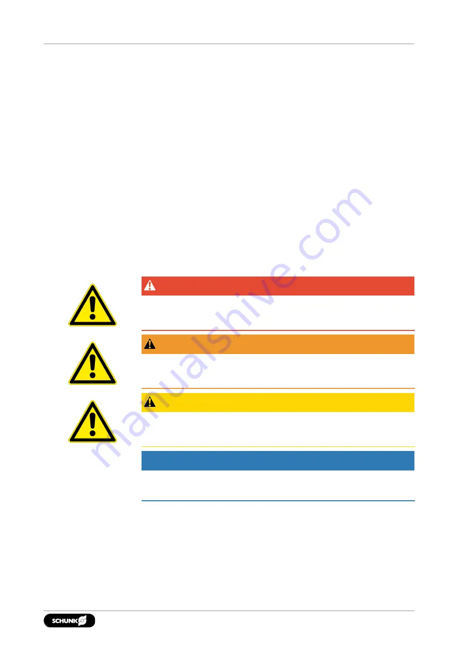
1.1.1 Presentation of Warning Labels

To make risks clear, the following signal words and symbols are
used for safety notes.

 DANGER

Dangers for persons!

Non-observance will inevitably cause irreversible injury or death.

 WARNING

Dangers for persons!

Non-observance can lead to irreversible injury and even death.

 CAUTION

Dangers for persons!

Non-observance can cause minor injuries.

NOTICE

Material damage!

Information about avoiding material damage.

5

05.00 | KSF3, KSF3-LH, KSF3-F | TANDEM Clamping Force Block | en | 1467140

Содержание TANDEM KSF3 100-Z

Страница 1: ...Translation of Original Operating Manual TANDEM Clamping Force Block KSF3 KSF3 LH KSF3 F Assembly and Operating Manual...

Страница 2: ...05 00 14 12 2022 en Dear Customer Thank you for trusting our products and our family owned company the leading technology supplier of robots and production machines Our team is always available to ans...

Страница 3: ...alfunctions 10 2 12 Disposal 11 2 13 Fundamental dangers 11 2 13 1 Protection during handling and assembly 11 2 13 2 Protection during commissioning and operation 12 2 13 3 Protection against dangerou...

Страница 4: ...4 Leak test 36 8 Sealing kits accessory kits and parts lists 37 8 1 Sealing kit lists 37 8 1 1 Piston chamber sealing kit 37 8 1 2 Monitoring sealing kit connection 38 8 2 Accessory kits 38 8 3 Parts...

Страница 5: ...ted under 1 1 2 6 are applicable NOTE The illustrations in this manual are intended to provide a basic understanding and may deviate from the actual version 1 1 1 Presentation of Warning Labels To mak...

Страница 6: ...M Jig machined positioning bores Z 1 2 Warranty If the product is used as intended the warranty is valid for 24 months from the date of delivery from the production facility or 500 000 cycles under th...

Страница 7: ...he chuck as a drill or as a cutting tool It is used in working environments that are not permissible Workpieces are not properly clamped Safety regulations are disregarded and persons are working at t...

Страница 8: ...nce cause higher surface pressures in the jaw guidance and can significantly reduce the clamping force Do not use welded jaws Reduce operating pressure for higher clamping points 2 6 Environmental and...

Страница 9: ...elevant standards and regulations Instructed person Instructed persons were instructed by the operator about the delegated tasks and possible dangers due to improper behaviour Service personnel of the...

Страница 10: ...ent prevention and environmental protection regulations regarding the product s application field 2 10 Transport Handling during transport Incorrect handling during transport may impair the product s...

Страница 11: ...open mechanism or movement area of the product during operation 2 13 1 Protection during handling and assembly Incorrect handling and assembly Incorrect handling and assembly may impair the product s...

Страница 12: ...ed monitors are not effective since the effect depends on the control and the current operating state of the drive Perform maintenance modification and attachment work outside of the danger zone defin...

Страница 13: ...ushing due to the chuck jaws approaching the workpiece during the clamping procedure when loading and unloading manually Prioritize automated loading Do not reach between the workpiece and the chuck j...

Страница 14: ...pressure bar 6 9 6 9 6 9 6 9 6 9 6 9 6 9 Repeat accuracy mm 0 01 0 01 0 01 0 01 0 02 0 02 0 02 max jaw height mm 60 60 60 60 100 150 200 Weight kg 1 5 4 3 8 5 12 5 25 5 39 4 84 5 Description KSF3 LH...

Страница 15: ...g 1 5 4 3 8 5 12 6 25 5 39 4 84 5 Clamping force is the arithmetic sum of the individual forces occurring at the chuck jaws at distance H see also catalog The maximum clamping force is achieved in the...

Страница 16: ...LH KSF3 F TANDEM Clamping Force Block en 1467140 Dimensions of the product 1 Optional Z variant 0 01 mm to clamping center 2 Clamping sleeve 0 04 mm to clamping center 3 Fitting screw 0 02 mm to clamp...

Страница 17: ...50 7 69 2 72 7 82 2 90 2 98 2 136 K 26 36 28 42 48 52 73 L 12 10 13 5 15 17 5 20 20 M 34 59 88 100 129 150 200 N M6 M8 M8 M10 M12 M12 M16 O 12 15 15 5 18 21 20 26 P 2 5 4 3 5 4 6 5 5 Q 8f7 10f7 10f7...

Страница 18: ...ity 12 9 Screw size M4 M5 M6 M8 M10 M12 M14 M16 M20 M24 Tightening torques MA Nm 5 9 15 32 62 108 170 262 510 880 Tightening torques for mounting the chuck piston onto the cylinder piston screw qualit...

Страница 19: ...g due to the product approaching the machine table during assembly Do not reach between the product and machine table during assembly CAUTION Danger of abrasions due to rough components of the product...

Страница 20: ...together with clamping sleeves item 85 and screws item 84 Assembly with fitting screws There are two fittings in the housing item 1 that along with the fitting screws item 82 are used to center the cl...

Страница 21: ...toring for jaw end position open 2 Air coupling in top jaw 1 3 Air coupling in top jaw 2 4 Dynamic pressure monitoring for jaw end position closed 5 Bottom connection for coolant drain or use for air...

Страница 22: ...table or on an adapter plate or for hose fittings Thread for pneumatic fitting front KSF3 KSF3 LH KS3 F 64 and 100 KSF3 KSF3 LH KSF3 F 140 160 200 and 250 KSF3 KSF3 LH KS3 F 315 M5 G1 8 G1 4 Hose fre...

Страница 23: ...e connections 6 7 for direct lubrication through the machine table These connections come sealed on delivery with set screws item 62 5 2 2 Dynamic pressure monitoring of the jaw end positions variant...

Страница 24: ...Connection Jaw end position open clamping force block closed Jaw end position closed clamping force block open Circuit diagram 1 NOTES For variants with a fixed jaw only the outer jaw end position can...

Страница 25: ...channels in the top jaw in order to clean the clamping and bearing surfaces by means of compressed air In doing so the transfer dimensions C D E and F must be observed Dynamic pressure monitoring of...

Страница 26: ...cuit symbols 5 3 directional control valve center position ventilated Pressure switch Actuation Pressure gauge Flow control valve Compressed air supply Jaw stroke open Jaw stroke close 1 Dynamic press...

Страница 27: ...ecessary oil quantity Chuck piston screw broken overload Send clamping system to SCHUNK for repair Piston rod or piston rod screw connection broken overload Send clamping system to SCHUNK for repair A...

Страница 28: ...sed too tightly against the housing Loosen the adjustment screws and readjust the monitoring piece 7 29 Monitoring functions of the jaw stroke positions do not work properly Possible cause Solution s...

Страница 29: ...parts Only use original spare parts from SCHUNK when replacing wearing parts spare parts Replacement of the housing and base jaws The base jaws and the guides in the housing are matched to each other...

Страница 30: ...OMAX plus can also be used as an alternative to microGLEIT LP 410 The specified clamping forces are however based exclusively on microGLEIT LP 410 as used by SCHUNK When using LINOMAX plus the clampin...

Страница 31: ...0 3 315 4 Central lubrication To use central lubrication the set screws of the factory sealed connections 6 7 must be removed For proper lubrication both supply lines must be connected The central lub...

Страница 32: ...ton and the cover strip may be dismantled For basic cleaning the upper part of the product base jaws with attachments cover strip and chuck piston must be disassembled cleaned and reassembled With the...

Страница 33: ...chuck piston 3 and base jaws 2 In the case of the PM variant note that the monitoring elements can fall off when the base jaws are removed Additionally for the KSF3 F variant Remove screw 68 Pull out...

Страница 34: ...eat all sliding surfaces with lubricant 7 3 30 Replace the seals of the monitoring if necessary 8 1 37 Assembly Assembly is done in the reverse order of disassembly In doing so observe the following P...

Страница 35: ...al Hand tighten the set screw 61 in the bore hole o Screw set screw 63 in both bore holes and hand tighten Jaw 2 monitoring closed jaw position Move base jaws to CLOSED position Screw the set screw 61...

Страница 36: ...off valve quick coupling supply line 2 Pressurize the clamping force block 3 Close the shut off valve and remove the supply line 4 Let the clamping force block sit clamped for 24 hours 5 After 24 hour...

Страница 37: ...s for the bottom connections are included in both sealing kits For spring actuated clamping force blocks KSF3 only the monitoring connection sealing kit provided by the customer is relevant 8 1 1 Pist...

Страница 38: ...hemselves with this Sealing kit ID Size 64 1470480 Size 100 1470390 Size 100 LH 1470468 Size 140 1470482 Size 160 1470397 Size 200 1508679 Size 250 1470398 Size 315 1508720 For included items see colu...

Страница 39: ...nical lubrication nipple 4 22 Sound absorber 2 23 Locking screw long stroke only 1x 2 24 Steel ball 2 I 26 Compression spring 4 I 27 Compression spring 2 I 28 Compression spring set 1 34 Cylindrical p...

Страница 40: ...7140 64 Countersunk screw ISO 14581 2 4 65 Cylindrical screw 9 10 13 66 Cylindrical screw 2 69 Screw 1 70 Set screw 1 81 Plug 4 82 Fitting screw 2 83 O ring DIN ISO 3601 4 X 84 Screw 4 85 Clamping sle...

Страница 41: ...brication nipple 4 22 Sound absorber 2 23 Locking screw 1 24 Steel ball 2 I 26 Compression spring 2 27 Compression spring 2 I 28 Compression spring set 1 34 Cylindrical pin 2 38 Sound absorber 1 40 Qu...

Страница 42: ...Screw 4 85 Clamping sleeve 2 86 Screw 8 87 O ring DIN ISO 3601 2 X I 10 X I 88 O ring DIN ISO 3601 7 X I 89 Set screw 2 93 Set screw 2 Parts list key a for all sizes y wearing part b for size 64 X inc...

Страница 43: ...bly drawings 9 1 KSF3 KSF3 LH A with variant PM B Centering with fitting screws C Centering with clamping sleeves D Centering with cylindrical pins Z variant 43 05 00 KSF3 KSF3 LH KSF3 F TANDEM Clampi...

Страница 44: ...wings 44 05 00 KSF3 KSF3 LH KSF3 F TANDEM Clamping Force Block en 1467140 9 2 KSF3 F A with variant PM B Centering with fitting screws C Centering with clamping sleeves D Centering with cylindrical pi...

Страница 45: ...48298 1457395 1457397 1448295 1457398 1457430 1457399 1448297 1460101 1514305 1514309 1514320 1514326 1514328 1514351 The partly completed machine may not be put into operation until conformity of the...

Страница 46: ...1448305 1457413 1457393 1457394 1448298 1457395 1457397 1448295 1457398 1457430 1457399 1448297 1460101 1514305 1514309 1514320 1514326 1514328 1514351 To be provided by the System Integrator for the...

Страница 47: ...characteristics of guards and protective devices 1 4 1 General requirements X 1 4 2 Special requirements for guards X 1 4 2 1 Fixed guards X 1 4 2 2 Interlocking movable guards X 1 4 2 3 Adjustable gu...

Страница 48: ...rature X The classification from Annex 1 is to be supplemented from here forward 2 Supplementary essential health and safety requirements for certain categories of machinery X 2 1 Foodstuffs machinery...

Страница 49: ......

Страница 50: ......

Страница 51: ......

Страница 52: ...GmbH Co Spanntechnik KG Lothringer Str 23 D 88512 Mengen Tel 49 7572 7614 0 Fax 49 7572 7614 1099 info de schunk com schunk com Folgen Sie uns I Follow us 12 2022 2022 SCHUNK GmbH Co KG 05 00 KSF3 KS...

Отзывы: