Maintenance and Care
02.00 | SWS-L | Assembly and operating manual | en | 0389037
41
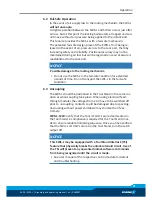
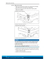
8.2.2.2 SWS-L-310 (Model Designator: SWK-L-310DM-...SM)
Lock and Unlock Sensor Assembly Replacement
1. Unscrew the sensor cable connector from the control/signal
module.
2. If present, remove the module(s) on the flat D.
3. Remove the two (2) M3 socket head cap screws that secure the
assembly to the SWK-L body.
4. Slide the sensor assembly out and discard. Visually check that o-
ring around sensor was removed with assembly.
NOTICE
The Lock and Unlock sensor assemblies are precision aligned
and permanently assembled at the factory. Do not attempt to
disassembled and re-build.
5. Apply Loctite 222MS to the new M3 socket head cap screws
supplied with the new sensor assembly.
6. Attach the new assembly to the SWK-L body by tightening the
M3 screws to 1.36 Nm of torque.
7. Re-attach cables and modules.
8. Confirm operation of the Unlock sensor by issuing the Unlock
command and then checking to see that the LED in the Unlock
sensor body is on.
9. Confirm operation of the Lock sensor by issuing the Lock
command to lock a SWA-L to the SWK-L and then checking to
see that the LED in the Lock sensor body is on.

