


Installation
22
02.00 | SWS-L | Assembly and operating manual | en | 0389037
• The interface plate must be properly designed to provide rigid
mounting to the SWK-L boss area.
• The plate design should take into account clearances required
for tool changer module attachments and accessories.
5.2 SWA-L
The SWA-L is attached to customer-supplied tooling. The SWA-L is
designed with mounting features such as a bolt and dowel holes.
These features are used to accurately position and secure the end-
effector. Most often an End- effector Interface Plate (EIP) is util-
ized to adapt the SWA-L to an end-effector that is not compatible
with the SWA-L mounting features. Custom End-effector Interface
Plates can be supplied by SCHUNK to meet customer requirements
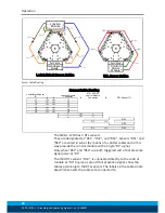
(refer to the drawings "Typical Installation" in the section above).
When the customer chooses to design and build an End- effector
Interface Plate, the following should be considered:
• The interface plate should be designed to include bolt holes for
mounting, dowel pins, and a boss that mates with SWA-L body
recess for accurate positioning.
•
SWS-L-310:
When using a locating boss, the race cover must be
removed.
•
SWS-L-210:
The locating boss height should not exceed 6.3mm.
If necessary, the race cover can be removed to allow for addi-
tional boss height.
• The thickness of the interface plate must be great enough to
provide the necessary thread engagement for the mounting bolts.
• The plate design should take into account clearances required
for SWS-L attachments and accessories.
• The End- effector Interface Plate should be designed with a hole
in its center to allow for manually returning the locking mechan-
ism to the unlocked position under adverse conditions (i.e. un-
intended loss of power and/or air pressure). The center access
hole should be kept small (minimum recommended hole dia-
meter: 25.4 mm) to prevent debris from contaminating the
locking mechanism while operating in dirty environments. Even
greater protection will result if the standard race cover with re-
movable access plug is used.
Note
: Thru hole diameter in plate:
14.3 mm. Grommet outside diameter: 22.5 mm.
•
SWS-L-1210:
The End- effector Interface Plate should be de-
signed with a set of holes in the center of each of the three lock-
ing mechanisms to allow for manually returning the locking
mechanisms to the unlocked position under adverse conditions
(i.e., unintended loss of power and/or air pressure). The center
access holes should be kept small (recommended hole dia-
meter: 25.4mm) to prevent debris from contaminating the lock-
ing mechanism while operating in dirty environments.