Maintenance and Care
02.00 | SWS-L | Assembly and operating manual | en | 0389037
39
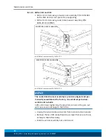
8.2.2 Lock and Unlock Sensor Assembly Replacement
8.2.2.1 SWS-L-210
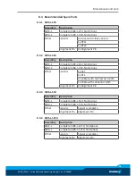
Sensor types
Determine what type of sensors the SWS-L uses:
Units using Sensor Assemblies
Units using Individual Sensors
NOTE
Turn air off before servicing sensors.
Units using Sensor as-
semblies
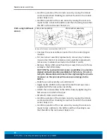
Lock and Unlock Sensor Assembly Replacement
Ø
Unscrew the sensor cable connector from the control/signal
module.
Ø
If present, remove the module(s) on the flat D.
Ø
Remove the two M3 socket head cap screws that secure the as-
sembly to the SWK-L body.
Ø
Slide the sensor assembly out and discard. Visually check that o-
ring around sensor was removed with assembly.
CAUTION The Lock and Unlock sensor assemblies are precision
aligned and permanently assembled at the factory. Do not at-
tempt to disassembled and re-build.
Ø
Apply Loctite 222MS to the new M3 socket head cap screws
supplied with the new sensor assembly.
Ø
Attach the new assembly to the SWK-L body by tightening the
M3 screws to 1.36 Nm of torque.
Ø
Re-attach cables and modules.

