


Assembly and Operating Manual
AGE-F-XY
– Compensation Unit with spring return
7
Date printed 28.12.2009
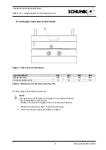
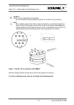
5.2 Mounting the module to the manipulator
Caution!
Breakage due to faulty assembly possible!
the max. depth of engagement on the robot side and tool side
(see Table 3, page 7).
The cylindrical pins required for fixing the module are not included in the scope of delivery.
The screws (Pos. 31) are pre.-mounted.
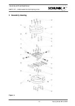
Figure 2: Mounting the module
1. Using two cylindrical pins, fix the module over the fixing bores.
2. Use an Allen key to tighten the mounting screws (item 31).
Type AGE-E-XY
031
040
063
080
Thread diameter and
max. depth of engagement Y, tool-side [mm]
M2,5
6 deep
M3
5 deep
M5/M6
9 deep
M6/M8
12 deep
Thread diameter and
max. depth of engagement X, robot-side [mm]
M2,5
5 deep
M3
4,5 deep
M4
6 deep
M5/M6
7 deep
Max. depth of engagement Z, robot-side [mm]
6
6
9
13
Cylindrical screw DIN 4762 /
Tightening torque (item 31)
M2,5
0,75 Nm
M3
1,27 Nm
M5
5,9 Nm
M8
24,6 Nm
Diameter of the cylindrical pins for fixing
the module [mm]
2
3
4
6
Table 3: Dimensions of mounting thread and centering


