Installation
EN-US · 30.30.01.02237 · 00 · 04/20
79 / 94
8 Installation
8.1 Installation Instructions
CAUTION
Improper installation or maintenance
Personal injury or damage to property
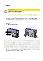
4
Prior to installation and before maintenance work, the compact terminal must be dis-
connected from the power supply and secured against unauthorized restart!
For safe installation, the following instructions must be observed:
1. Use only the connectors, mounting holes and attachment materials that have been provided.
2. Firmly connect and secure pneumatic and electrical line connections to the compact terminal.
3. Ensure that there is adequate installation space in the area where the product will be installed.
8.2 Mounting
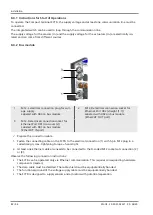
The SCTSi may be installed in any position.
5
1
2
3
4
8
9
6
7
1
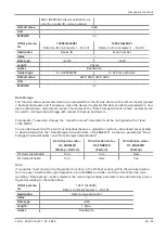
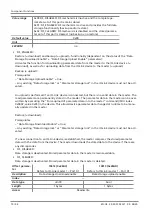
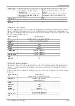
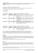
Compressed air connection, 1/4" thread
2
M12-D electrical connection for Ethernet
Port X02 (straight [1:1])
3
M12-D electrical connection for Ethernet
Port X01 (crossover [x])
4
Alternative compressed air connection
1/4" thread (2 Nm)
5
M12-L electrical connection for voltage
supply. Labeled with X03 on bus module.
6
Electrical connection socket M12-A Port
X01 to X04 for IO-Link devices
7
Electrical connection socket M12-A Port
X01 to X04 for digital sensors
8
End plate with two mounting holes (4
Nm)
9
Vacuum connection, 1/8" thread (2 Nm)
4
Mount the Compact terminal SCTSi on the end plates (8) using two M5 screws and washers each. The
maximum recommended tightening torque is 4 Nm.

