EN
5 DESIGN AND FUNCTION
5.
DESIGN AND FUNCTION
5.1
Overview
2
3
8
4
5
6
7
1
9
10
11
12
13
LIFT
SET
RELEASE
FA
N
NI
NG
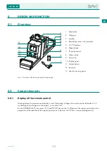
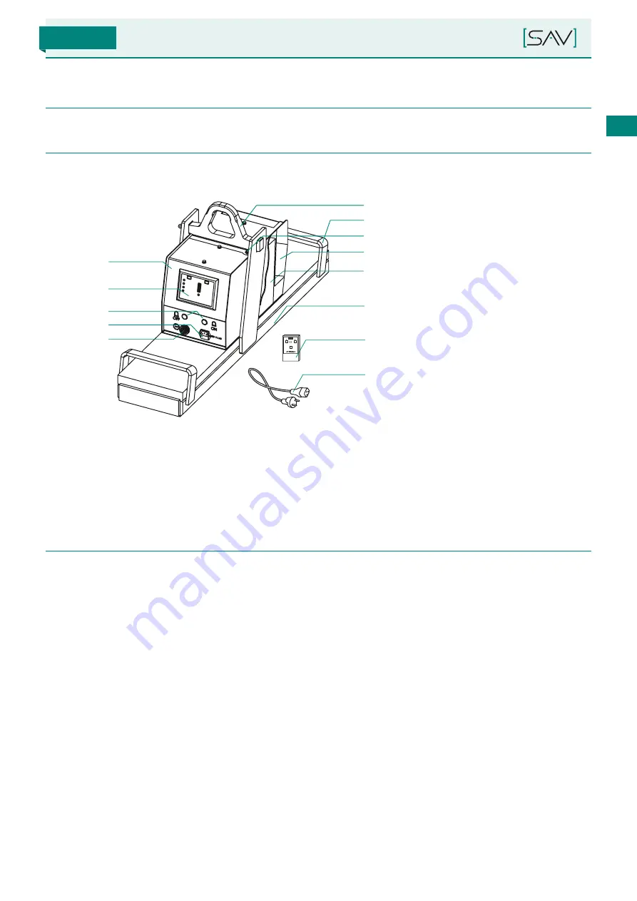
1 Feed cable
2 Lifting eye
3 Handles
4 Rear battery cover with type plate
5 12 V DC battery
6 Magnet body
7 IR remote control
8 Safety switch
9 Front cover
10 Display panel
11 Control buttons
12 Input port
13 Acoustic warning signal
Fig. 5: Overview of the battery-powered lifting magnet
5.2
Control elements
5.2.1
Display of the remote control
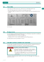
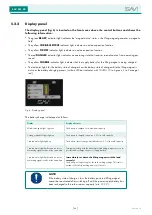
Warning display if the remote control battery is low If the battery voltage of the remote control falls below 7.3 V,
two flashing lines will appear in the display – see section 3.8.2.
For the VARIABLE FORCE (see section 7.3.1) and TIP-OFF (see section 7.3.2) functions, the remote control shows the
progression of the reduction of the magnetic power on a scale from 0 to 99 (this is not a percentage value).
SAV 531.42
Version 1.0
[
83
]
Содержание SAV 531.42
Страница 3: ...BATTERIE LASTHEBEMAGNETE BETRIEBSANLEITUNG Version 1 0 DE SAV 531 42 just experts ...
Страница 56: ...SAV 531 42 NOTIZEN Version 1 0 56 ...
Страница 57: ...BATTERY POWERED LIFTING MAGNETS OPERATING INSTRUCTIONS Version 1 0 EN SAV 531 42 just experts ...
Страница 110: ...NOTES SAV 531 42 Version 1 0 110 ...
Страница 111: ......


