03/31/14
Passport 1000 P2 WiFi Exit Device
21 1-800-810-WIRE • www.sargentlock.com • A8012F
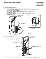
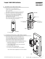
Inside of Door
Wire Cover
(2) #6 x 1/2”
Flat Head Security
Torx Wood Screws
(2) 3/32” Diameter by
1/2” Deep Holes
Fig. 8A
This Side Down
Fig. 8B Detail
Back Side of
Wire Cover Plate
1. Position the wire cover plate above the
chassis cover and covering the wire channel.
Mark hole positions.
Note: Make sure stamped side of plate is against door.
2. Drill (2) 3/32” diameter by 1/2” deep holes (Fig. 8A).
3. Cover wires with cover plate by securing plate
to door directly above chassis (note orientation)
using two (2) #6 x 1/2” flat head security
torx wood screws (Fig. 8B).
Note: Position lower edge of cover plate against the
cover to ensure that no wires are visible.
8 Install Wire Cover (Wood Doors Only)
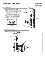
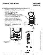
9 Install Outside Escutcheon (with Optional Gasket)
Note: Gasket optional, for non-fire rated doors only
.
For non-fire rated door applications, an optional gasket
(Part number 52-0782) may be used as a weather seal
between the escutcheon and the outside door surface.
Peel off adhesive backing and attach to (outside) escutcheon.
1. Position the outside escutcheon, aligning the posts
with the door prep (Fig. 9).
2. On the inside of the door, position the mounting plate
over the indicated holes.
3. Feed reader cable through opening.
4. The cable from the lockbody feeds from the bottom.
Note: Cable lengths exaggerated for illustrative purposes.
Fig. 9


