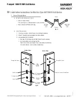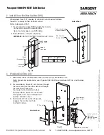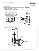
03/31/14
Passport 1000 P2 WiFi Exit Device
13 1-800-810-WIRE • www.sargentlock.com • A8012F
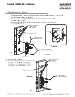
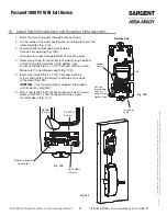
Fig. 11B
DPS
Reader
Cable
Mounting Plate
Position ground
ring terminal
upright, then
tighten screw
Lock body cable
11 Installation of Connectors
CAUTION - Do not touch or allow debris to enter connector contacts.
Secure the following connectors to their respective terminals (Fig. 11A, B ):
A. Secure the 10-pin lock body assembly connector.
*NOTE: Optional 2-pin external 12-24VDC power connector.
B. Tuck excess cable into wire hole on inside of door.
C. Finish securing mounting plate and reader to door by fully
tightening through-bolts on inside of door.
Note: Ensure groundring is positioned upright.
D. Secure the 24-pin card reader connector.
Wire Positioning:
Please follow these steps prior to installing
inside escutcheon to prevent any damage
caused by pinching wires:
Lock
Body
(10-pin)
9-24VDC
Power*
Reader
(24-pin)
Fig. 11A
Board-to-Board
Connector
DPS


