Access to the clock can be controlled by
changing the clock’s connection mode.
There are two modes:
Connection Mode and Direct Mode
The functions of each mode are as
follows:
Direct Mode
- In Direct Mode, a clock
acts as its own Wi-Fi Access Point and
can be accessed directly from any Wi-Fi
capable computer in range of it.
While in Direct Mode, the clock is
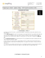
accessible through IP address to
192.168.240.1. A Wi-Fi synchronized
clock will revert to whichever IP address
is listed on the Network Settings
address page once Direct mode has
been ended.
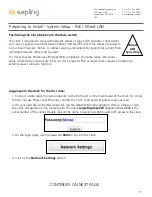
Connection Mode
- In connection
mode, a properly configured Wi-Fi
clock is accessible over the facility’s
network, and will appear on Monitor
software located on the same subnet.
This mode is only available if the
user ordered the clock with Wi-Fi
Synchronization.
The clock is shipped in Direct Mode.
All clocks that do NOT use Wi-Fi
synchronization will continually
broadcast in Direct Mode. Wi-Fi
clocks that are not connected to the
network will always be accessible
in Direct Mode.
For clocks that use Wi-Fi Synchronization, once a network has been set by the user, the clock will always start in Connection
Mode.
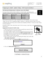
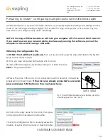
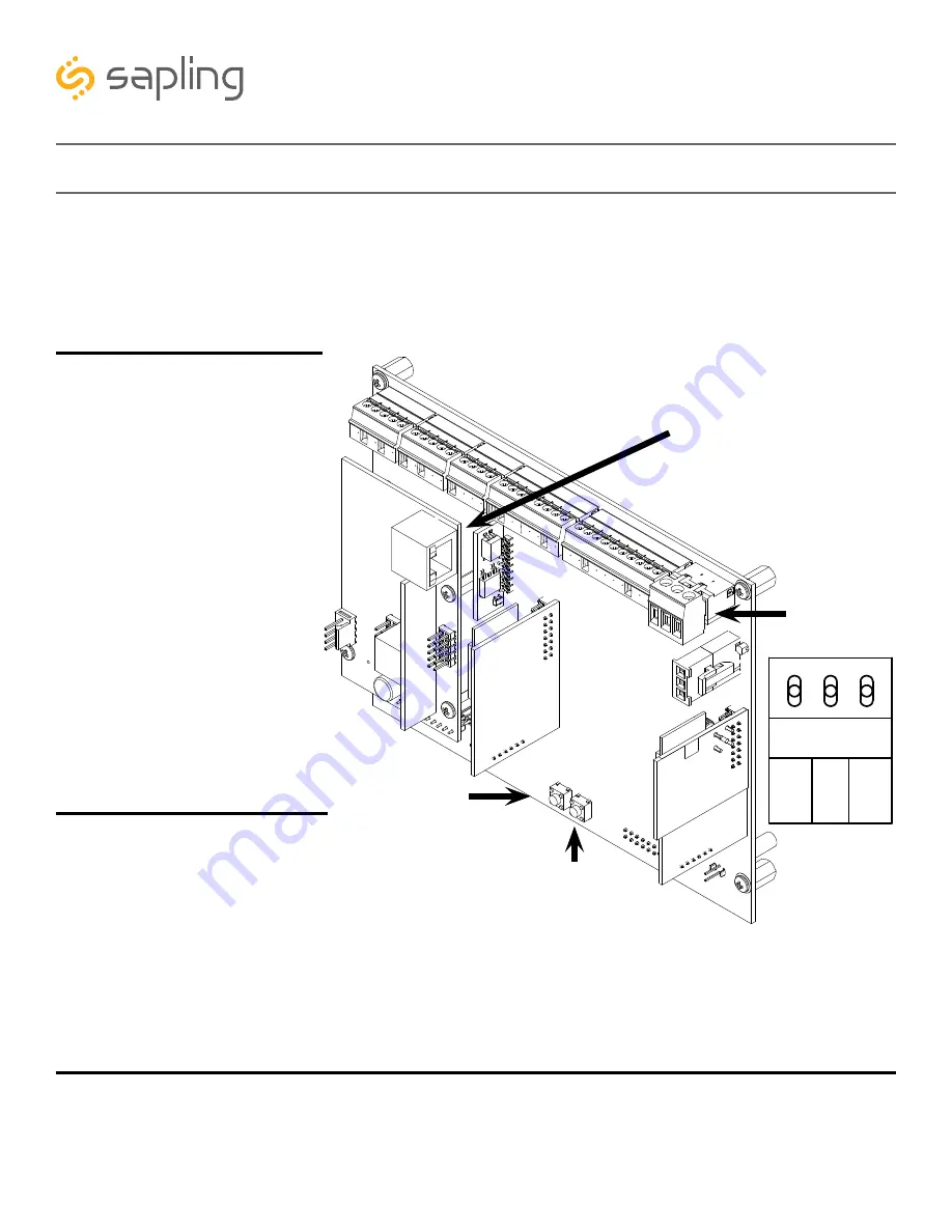
A clock in Connection Mode can be placed into Direct Mode by pressing SW1 on the main board twice.
If
performed correctly, the word “DIRECT” will appear on the display for a few seconds. On a 4-digit clock, only the letters
“DIRE” will appear. In this mode, a clock will wait four minutes for the user to access it before automatically deactivating its
Wi-Fi transceiver. Direct Mode will automatically activate if the network settings were not correctly entered, or if the clock
cannot access the network.
7
The Sapling Company, Inc.
670 Louis Drive
Warminster, PA 18974
USA
P. (+1) 215.322.6063
F. (+1) 215.322.8498
www.sapling-inc.com
Initial Configuration of the clock requires access to the main board, regardless of which system
you have purchased.
To access the main board, use a Phillips-head screwdriver to remove the screws surrounding the wiring
panel. Store these screws in a safe place, as you will need to reinstall the panel later on.
During configuration, you will need to power the main board and may be asked to operate a pair of
push-button switches. Refer to the diagram below.
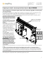
Preparing to Install - Accessing the Main Board -
ALL SYSTEMS
RJ45 for Data/PoE
(wired LAN sync only)
Power
SW1
SW2
3.3V, 100MA
3.3V, 100MA
Timer RX
Temp RX
Common
Timer TX
Temp TX
Not Used
Not Used
Input B+
Output A-
Output B+
Rly1 NO .5A 120vac/24vdc
Rly2 NO .5A 120vac/24vdc
User 1 Input
User 2 Input
User 3 Input
User 4 Input
Common
5V, 40MA
9 -12V, 40MA
Dukane Pulse
Dukane Reset
24Vac Sync
120Vac Sync
AC/DC Com
AUX
5V Dry Cont
(-) Neutral
(+) Line
Earth
1
1
1
1
1
J4
J5
J7
J10
J11
J9
RS485
Common
Input A-
5
5
4
8
10
24 VAC/DC
110/220 VAC
When ready, go to the “Preparing to Install - System Setup” page for your system.


