33
The Sapling Company, Inc.
670 Louis Drive
Warminster, PA 18974
USA
P. (+1) 215.322.6063
F. (+1) 215.322.8498
www.sapling-inc.com
Buzzer - Optional Accessory
To activate the buzzer with a countdown,
log on to the web interface and perform the following
actions:
1. Click on the “Input and Relay Settings” button, followed by the “End Countdown” button. Find the
drop-down menu next to “On Countdown complete, close” and select “Relay 2”
2. In “for ____ seconds” set the amount of time that you wish the buzzer to sound when the
countdown ends. The number must be a whole number from 1 to 60.
3. Press the Submit button.
To activate the buzzer without a countdown,
click on the Input and Relay Settings button, followed
by either the Elapsed Timer or Inputs button. For the button or input that you wish to trigger the buzzer,
set the Action as Relay 2. Press the submit button after inputting these settings.
Pressing the button on the Elapsed Timer Control Panel or activating the input will cause the Relay to
toggle to the opposite of its current setting and remain that way until the button or input is activated
again. If the Buzzer is currently off, this will turn the buzzer on. If the buzzer is currently on, this will turn
the buzzer off.
(
IMPORTANT:
Detach clock from power source before installing new circuitry. DO NOT add new circuitry
while the clock is operating)
The Buzzer accessory kit (
L-BUZZ-3300-1
)
comes with all wires already installed in the correct
ports for the J10 and J11 connectors, and installation can be completed by attaching these
connectors to the J10 and J11 sockets on the clock main board.
If you wish to set up the buzzer on existing connectors, use the instructions below.
You will need the buzzer, the small yellow 26AWG wire, a wire stripper, and an eyeglass
screwdriver.
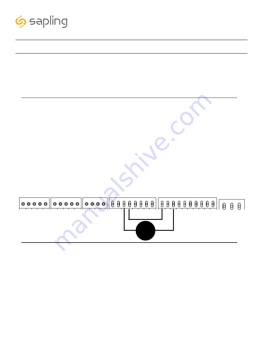
1) Use the eyeglass screwdriver to open connector ports J10-3, J10-4, J11-1, and J11-3. Refer to the diagram
below for the position of each port.
2) Connect the red wire on the buzzer to port J11-3.
3) Connect the black wire on the buzzer to port J10-3 (relay 2) on the main board.
4) Strip the ends of the extra yellow wire and use it to connect J10-4 (relay 2) to J11-1.
5) Use the eyeglass screwdriver to close all four ports. Tug gently on each wire to confirm that each wire
end is secure.
3.3V, 100MA
3.3V, 100MA
Timer RX
Temp RX
Common
Timer TX
Temp TX
Not Used
Not Used
Input B+
Output A-
Output B+
Rly1 NO .5A 120vac/24vdc
Rly2 NO .5A 120vac/24vdc
User 1 Input
User 2 Input
User 3 Input
User 4 Input
Common
5V, 40MA
9 -12V, 40MA
Dukane Pulse
Dukane Reset
24Vac Sync
120Vac Sync
AC/DC Com
AUX
5V Dry Cont
100-240vac L1
100-240vac L2
Ground
1
1
1
1
1
J4
J5
J7
J10
J11
J9
RS485
Common
Input A-
5
5
4
8
10
Black
Red
3
4
1
3
Yellow
Buzzer

