


58
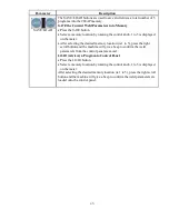
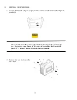
Remove four mounting screws from the control panel (see Figure 7-2).
b)
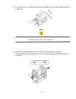
Access the VRD control by gently prying back the front panel controls to reveal the
VRD on/off potentiometer (see Figure 7-2).
Do not pull back the front panel with excessive force as this may unplug the
control PCB. Plugging the control PCB back into the front panel controls
can only be achieved by removing the side covers.
Figure 7-2 VRD ON/OFF Step B, C
WARNING:
The VRD ON/OFF trim potentiometer MUST ONLY be positioned fully
clockwise OR fully counter clockwise as the VRD function will be
unknown for every other position.
Содержание SANARG 200AP
Страница 2: ......
Страница 4: ......
Страница 8: ......
Страница 24: ...24 PAGE LEFT INTENTIONALLY BLANK ...
Страница 35: ...35 Figure 3 2 Electrical Input Connections 200AP ...
Страница 56: ...56 6 4 4 SPOT MODE Contactor Hot start Iw ON ON HF Solenoid Output current ON Preflowtime Hot cur Spot time ...
Страница 60: ...60 PAGE LEFT INTENTIONALLY BLANK ...
Страница 66: ...66 PAGE LEFT INTENTIONALLY BLANK ...
Страница 79: ...79 PAGE LEFT INTENTIONALLY BLANK ...
Страница 80: ...80 10 1 INTERCONNECT DIAGRAM 200AP ...
Страница 81: ...81 ...
Страница 82: ...82 10 2 EXPLODED VIEW 200AP ...
Страница 83: ...83 ...
Страница 84: ...84 PAGE LEFT INTENTIONALLY BLANK ...
Страница 89: ...PAGE LEFT INTENTIONALLY BLANK ...


