


39
SECTION 4- OPERATOR CONTROLS, DIMENSIONS & OUTLINE
4.0
OPERATOR CONTROLS, DIMENSIONS & OUTLINE
4.1
DIMENSIONS AND OUTLINE
The figure below shows the dimensions and the outline of the SanRex model 200AP.
FIGURE 4-1 : Model 200AP Dimensions and Controls
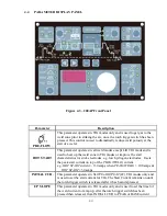
4.2
OPERATOR CONTROLS, LOCATION AND FUNCTIONALITY
Refer to the figure above for the corresponding reference numbers.
1. Control Knob
This knob is used to change the value of the selected weld parameter, rotate it clockwise to
increase the selected weld parameter and counter clockwise to decrease the value. The value
is indicated on the digital meter. Pushing the knob in previews the actual welding voltage
while welding.
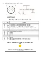
2. 14-PIN Remote Control Receptacle
The 14-PIN Remote Control Receptacle is used to connect a remote current control devices
to the welding Power Source. To make the connection, align the keyway, insert plug, and
rotate threaded collar fully clockwise. See Section 4.3 for details description of the 14-PIN
Remote Control Receptacle.
Содержание SANARG 200AP
Страница 2: ......
Страница 4: ......
Страница 8: ......
Страница 24: ...24 PAGE LEFT INTENTIONALLY BLANK ...
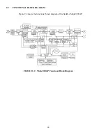
Страница 35: ...35 Figure 3 2 Electrical Input Connections 200AP ...
Страница 56: ...56 6 4 4 SPOT MODE Contactor Hot start Iw ON ON HF Solenoid Output current ON Preflowtime Hot cur Spot time ...
Страница 60: ...60 PAGE LEFT INTENTIONALLY BLANK ...
Страница 66: ...66 PAGE LEFT INTENTIONALLY BLANK ...
Страница 79: ...79 PAGE LEFT INTENTIONALLY BLANK ...
Страница 80: ...80 10 1 INTERCONNECT DIAGRAM 200AP ...
Страница 81: ...81 ...
Страница 82: ...82 10 2 EXPLODED VIEW 200AP ...
Страница 83: ...83 ...
Страница 84: ...84 PAGE LEFT INTENTIONALLY BLANK ...
Страница 89: ...PAGE LEFT INTENTIONALLY BLANK ...


