


42
4.3
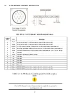
14-PIN REMOTE CONTROL RECEPTACLE
FIGURE 4-2 : 14-PIN Remote Control Receptacle Layout.
Socket
Pin
I/O
Function
A
Input
Torch Switch Input. To energize weld current, connect pins A & B.
B
Input
Torch Switch Input. To energize weld current, connect pins A & B.
C
Output
+10VDC signal connects to high side of 1k ohm remote control potentiometer.
D
GND
Zero ohm (minimum) connection to low side of 1k ohm remote control potentiometer.
E
Input
Wiper arm connection to 1k ohm remote control potentiometer, (0 to +10VDC signal)
F
N/C
Not used
G
GND
Internally connected to chassis ground.
H
N/C
Not used
I
N/C
Not used
J
N/C
Not used
K
N/C
Not used
L
N/C
Not used
M
Output
OK TO MOVE (current detect signal, dry contact closure to pin N)
N
Output
OK TO MOVE (current detect signal, dry contact closure to pin M)
TABLE 4-1 : 14-PIN Remote Control Receptacle Pin-Out Description.
NOTE:
The 14-PIN Remote Control Contactor has the capability to operate by
shorting pin set A-B
Содержание SANARG 200AP
Страница 2: ......
Страница 4: ......
Страница 8: ......
Страница 24: ...24 PAGE LEFT INTENTIONALLY BLANK ...
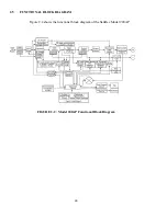
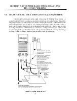
Страница 35: ...35 Figure 3 2 Electrical Input Connections 200AP ...
Страница 56: ...56 6 4 4 SPOT MODE Contactor Hot start Iw ON ON HF Solenoid Output current ON Preflowtime Hot cur Spot time ...
Страница 60: ...60 PAGE LEFT INTENTIONALLY BLANK ...
Страница 66: ...66 PAGE LEFT INTENTIONALLY BLANK ...
Страница 79: ...79 PAGE LEFT INTENTIONALLY BLANK ...
Страница 80: ...80 10 1 INTERCONNECT DIAGRAM 200AP ...
Страница 81: ...81 ...
Страница 82: ...82 10 2 EXPLODED VIEW 200AP ...
Страница 83: ...83 ...
Страница 84: ...84 PAGE LEFT INTENTIONALLY BLANK ...
Страница 89: ...PAGE LEFT INTENTIONALLY BLANK ...


