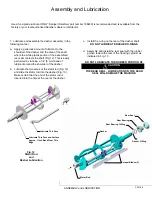
Spigot Handle
Spigot Plunger
(3) O-Rings
Front Plate O-Ring
DO NOT LUBRICATE
Front Plate Knob
Front Plate Knob
Faspin
Front Plate
Pressure Relief Plug
with 2 O-rings
(2) O-Rings
DISASSEMBLY and CLEANING
Fig. 7
O-Ring
PAGE 4
CAUTION
DO NOT USE ANY TOOLS OR SHARP OBJECTS TO RE-
MOVE ANY O-RINGS FROM THIS MACHINE. SHARP OB-
JECTS WILL DAMAGE THE O-RINGS.
Disassembly and Cleaning Procedure
1. Turn lever on “Smart Coupler” to the "OFF" position.
Untap barrel and connect the 5 gallon cleaning canister
filled with fresh cool water.
2. Place Auto/Clean switch in "CLEAN" position.
3. Turn the lever on the "Smart Coupler" to the "CLEAN"
position.
4. Draw off and discard the frozen contents of the freezing
cylinder.
5. Place the Auto/Clean switch in the "OFF" position.
6. Draw off the liquid contents of the freezing cylinder with
the relief valve in the upward (open) position to aid in
draining of the cylinder.
7. Untap canister and remove any residual pressure in the
cylinder by opening the spigot.
8.
BE SURE THE AUTO/CLEAN SWITCH IS IN THE
“OFF” POSITION PRIOR TO REMOVING THE FRONT
PLATE AND DASHER ASSEMBLIES.
9. Remove the front plate (Fig. 6) by turning the black plas-
tic knobs in a counterclockwise direction.
Disassemble the front plate in the following manner:
a. Remove the faspin and spigot handle.
b. Remove the front plate o-ring.
c. With the spigot handle removed, push the spigot
plunger out the top of the front plate and remove all
lubricant from the spigot plunger.
d. Remove the three o-rings from the spigot plunger
(Fig. 7) by grasping the part with one hand and with
a dry cloth in the other hand, squeeze the o-ring up-
ward. When a loop is formed, grasp the o-ring with
the other hand and roll it out of its groove and off the
spigot plunger .
e. Remove pressure relief plug and remove the two O-
rings from the plug.
9. Remove the dasher assembly (Fig. 8) being careful not to
damage the scraper blades, then disassemble in the follow-
ing manner:
a. Remove the rear seal assembly
b. Remove the stator rod from the dasher.
c. Remove the blades from the dasher by first rotating
blade upward and then unsnapping one end from the
support rod (see Fig. 9).
d. Remove o-ring from the rear of the dasher.
e. Separate the GREY rubber rear seal from the rear bear-
ing and remove the rear bearing O-ring.
Fig. 6
Front Plate
Fig. 8
Scraper Blades (2)
Dasher
Stator Rod
Rear Bearing O-Ring
Rear Seal
Dasher O-Ring
BLADES
MUST BE
REMOVED FOR CLEANING
Rear Bearing
Plunger O-Rings
Содержание A7081HEP
Страница 2: ......
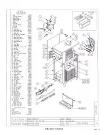
Страница 17: ...PAGE 16 ASSEMBLY DIAGRAM ...
Страница 18: ...Notes ...
Страница 19: ...Service Log ...


