background image


INTRODUCTION and INSTALLATION 

1.  Install the legs using the instructions on the shipping 
carton. 
 
2.  Place the machine in the desired location and level 
the unit by turning the bottom part of each leg clockwise 
or counterclockwise (Fig. 2). The machine 

MUST

 be 

level to operate properly. 

THESE UNITS MUST NOT BE OPERATED WITHOUT 

THE LEGS INSTALLED UNLESS THE MACHINE IS 
SUPPLIED WITH A COUNTERTOP MOUNTING PAD 
OR SEALED TO THE COUNTERTOP.


3.   
A  minimum 6” (152 

mm) clearance 

must  be  

maintained  at  

the rear and sides 

of the machine 

for adequate 

ventilation.   


4.  Electrical and refrigeration specifications are located 
on the data plate on the rear panel of the machine.  
Consult local authorities for information regarding 
plumbing and electrical codes in your area.   
 
Insure that the unit is in the off position and plug it into a 
115 volt, 15 amp or 20 amp receptacle. 
 

Note:  All SaniServ machines should have their own 
dedicated circuits to prevent low voltage conditions 
caused by other operating equipment. 


FAILURE TO PROVIDE FOR PROPER EARTH 
GROUND ACCORDING TO LOCAL ELECTRICAL 
CODES COULD RESULT IN SERIOUS  ELECTRICAL  
SHOCK OR DEATH.  DO NOT USE EXTENSION 
CORDS.  INSTALL THE PROPER SIZE WIRE FOR 
THE REQUIRED MACHINE AMPS.  BE CERTAIN TO 
OBSERVE LOCAL CODES IN SELECTING WIRE OR 
CORD SIZE AND TYPE. 


Installation 

Fig. 2 

Leg Installation 

Minimum Clearance 

4”(102 mm) for 

Counter Top Models  

This manual provides a description of the SaniServ Pressurized Frozen Beverage Dispenser.  It has been prepared to 
assist in the training of personnel on the proper installation, operation, and maintenance of the machines. 
 
Read and fully understand the instructions in this manual before attempting to install, operate, or perform routine 
maintenance on the machines.  
 
Initially, the following sections of the manual must be performed in sequence:  


1.  Installation  

4.  Operation 


2.  Installer's Preoperational Check 

5.  Disassembly & Cleaning 


3.  Initial Start-up Preparation   

6.  Assembly & Lubrication 


Introduction 

PAGE   1 

WARNING


WARNING


IMPORTANT


DO NOT TURN MACHINE ON UNTIL THE 
INSTALLER’S PRE-OPERATIONAL CHECK  
SECTION IS COMPLETE. 

Содержание A7081HEP

Страница 1: ... Reliability from the team that Serves the Best SaniServ P O Box 1089 Mooresville Indiana 46158 Operation Manual Pressurized Frozen Beverage Dispenser Model A7081HEP SaniServ An AFFINIS GROUP Company ...

Страница 2: ......

Страница 3: ... responsibility to maintain the Service Record located on the inside rear cover of this manual An accurate record of service performed can greatly expedite troubleshooting of problems and significantly reduce repair costs PARTS Always order parts from your SaniServ dealer or distributor When ordering replacement parts specify the part numbers give the description of the part the model number and t...

Страница 4: ...age conditions caused by other operating equipment FAILURE TO PROVIDE FOR PROPER EARTH GROUND ACCORDING TO LOCAL ELECTRICAL CODES COULD RESULT IN SERIOUS ELECTRICAL SHOCK OR DEATH DO NOT USE EXTENSION CORDS INSTALL THE PROPER SIZE WIRE FOR THE REQUIRED MACHINE AMPS BE CERTAIN TO OBSERVE LOCAL CODES IN SELECTING WIRE OR CORD SIZE AND TYPE Installation Fig 2 Leg Installation Minimum Clearance 4 102 ...

Страница 5: ... start Check to see that the refrigeration system is operating by feeling the inside of the freezing cylinder It should turn cold within one minute 3 Set the Auto Clean switch to the OFF position 4 Install the Dasher Assembly Fig 3 inserting it in the freezing cylinder and pushing toward the rear of the cylinder while rotating the assembly until it seats into the drive at the rear of the cylinder ...

Страница 6: ...f plug Close Pressure Relief Plug 3 Turn Auto Cleanout to the AUTO position 4 When the machine cycles off draw a sample of product and check for proper consistency Repeat this step two times 5 If the product is too soft or two stiff refer to the section on consistency adjustment Operation Fig 4 Pressure Relief Plug Disassembly and Cleaning CONSULT YOUR LOCAL HEALTH AGENCY FOR LOCAL CLEANING AND SA...

Страница 7: ...ig 6 by turning the black plas tic knobs in a counterclockwise direction Disassemble the front plate in the following manner a Remove the faspin and spigot handle b Remove the front plate o ring c With the spigot handle removed push the spigot plunger out the top of the front plate and remove all lubricant from the spigot plunger d Remove the three o rings from the spigot plunger Fig 7 by grasping...

Страница 8: ... a In the first partition a solution of water and anti bacterial dishwashing detergent b In the second partition clear rinse water c In the third partition sanitizing rinse solution equivalent to 200 parts per million PPM Chlorine residual 13 Pour a portion of the detergent solution in the expansion chamber and clean the chamber and freezing chamber with the brush provided 14 Place all removable i...

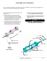
Страница 9: ... Lubricate and assemble the dasher assembly in the following manner a Apply a generous amount of lubricant to the shoulder of the dasher and the area of the shaft where the white plastic portion of the assembled rear seal contacts the shaft Fig 12 This is easily performed by running a 1 4 6 mm bead of lubricant around the shoulder of the dasher b Lubricate the two areas of the stator rod Fig 12 an...

Страница 10: ...he dasher assembly into the freezing cylinder as far as possible Fig 17 being careful not to damage the scraper blades Damage will occur to the scraper blades and the dispenser will not operate properly if the scraper blades are installed facing in a clockwise direction Fig 18 Note The stator rod has been deleted from Fig 17 and Fig 18 for clarity only The stator rod must be installed for proper m...

Страница 11: ...ug into the front plate Fig 20 making certain that the spigot handle slot is aligned to the front C Insert the spigot handle and secure with the faspin d Install the front plate o ring DO NOT LUBRICATE THE FRONT PLATE O RING e Secure the front plate assembly with the two plastic knobs Simultaneously turn the knobs in a clockwise direction Tighten the knobs evenly DO NOT tighten one knob all the wa...

Страница 12: ... 2 Do not over tighten the knobs 3 Always tighten the front plate knobs evenly Do not attempt to turn one knob all the way down and then the other Doing so will bind the front plate and result in breakage 4 Improper installation of the stator rod can cause breakage The stator rod must be properly seated in the dasher before installing the front plate If the stator rod is improperly installed subse...

Страница 13: ...before panels guards or protective covers are removed Once the panels guards are removed an adjustment is made protective panels guards are replaced power is restored to the machine and the consistency setting is tested This process is repeated as necessary until the desired product consistency is obtained The mechanical control system is a very simple method of controlling the consistency of the ...

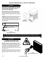
Страница 14: ... panels and clean all parts inside of the machine including the base side panels fan blades condensers etc DISCONNECT THE MACHINE FROM ITS POWER SOURCE S BEFORE PERFORMING ANY ROUTINE MAINTENANCE PERSONAL INJURY OR DAMAGE TO THE MACHINE COULD RESULT IF THIS PRACTICE IS NOT OBSERVED Daily Inspect the machine for signs of product leaks past seals and gaskets If proper assembly does not stop leaks ar...

Страница 15: ... emery cloth 7 Reinstall the belt idler arm NOTE BE CERTAIN NOT TO OVERTIGHTEN THE LOCKING NUT ON SOME UNITS IT IS POSSIBLE TO OVERTIGHTEN THE LOCKING NUT AND CAUSE THE IDLER ARMS TO BIND THE ARMS SHOULD MOVE FREELY 8 Repeat the process for the torque idler arm 9 Install the belt making certain that there is no grease on the belt or pulleys Step to the side of the unit and view the belt to determi...

Страница 16: ...spect the torque arm for free movement 2 Check the torque switch It must click when depressed See Consistency Adjustment 3 Inspect the condenser for dirt or obstruction See Routine Maintenance 4 Check for proper clearance around the machine If equipment leaks 1 Check o rings and seals Replace as necessary 2 Check for proper lubrication Lubricate per instructions If unit freezes up 1 Damage from pr...

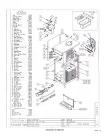
Страница 17: ...PAGE 16 ASSEMBLY DIAGRAM ...

Страница 18: ...Notes ...

Страница 19: ...Service Log ...

Страница 20: ... Reliability from the team that Serves the Best SaniServ P O Box 1089 Mooresville Indiana 46158 P N 82259 Rev A 021303 SaniServ An AFFINIS GROUP Company ...

Отзывы: