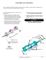
Spigot Handle
Spigot Plunger
(3) O-Rings
Front Plate O-Ring
DO NOT LUBRICATE
Front Plate Knob
Front Plate Knob
Faspin
Front Plate
Pressure Relief Plug
(2) O-Rings
2. Lubricate and assemble the front plate assembly in
the following manner:
a. Install the three o-rings on the spigot plunger AND
two O-rings on the Pressure Relief Plug by
rolling them onto the plunger. Seat the o-rings in
the grooves. Be certain that they are not twisted.
Smooth the lubricant into the grooves and over
the sides of the plunger and Pressure Reief Plug
assemblies (Fig. 21).
b. Slide the lubricated spigot plunger and Presure
Relief Plug into the front plate (Fig. 20) making
certain that the spigot handle slot is aligned to the
front.
C.
Insert the spigot handle and secure with the faspin.
d. Install the front plate o-ring.
DO NOT LUBRICATE THE FRONT PLATE O-RING
e. Secure the front plate assembly with the two
plastic knobs. Simultaneously, turn the knobs in a
clockwise direction. Tighten the knobs evenly.
DO
NOT
tighten one knob all the way down and
then the other. Doing so may result in front plate
breakage. Only moderate force is required.
DO
NOT
over tighten. Close the spigot plunger.
5. Install the drip tray and drip tray insert .
PAGE 8
Fig. 19
Dasher with Blade (Front View)
Fig. 20
Front Plate Assembly
ASSEMBLY and LUBRICATION
Approximately 1/8 inch
Exposed
Fig. 21
Spigot Plunger / Relief Plug
Lubrication
Lubricate This
Area
Lubricate This
Area
Содержание A7081HEP
Страница 2: ......
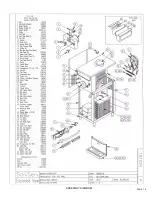
Страница 17: ...PAGE 16 ASSEMBLY DIAGRAM ...
Страница 18: ...Notes ...
Страница 19: ...Service Log ...


