background image

98  S&C Instruction Sheet 461-504

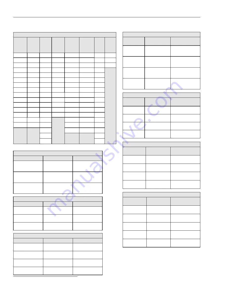
Fuse Link

Ampere Rating

K-Speed T-Speed QA/QR

KS

NE 

(N-Speed 

McGraw- 

Edison)

NK 

(N-Speed 

Kearney)

ST

CO

6K

6T

3QR

10KS

5NE

5NK

5ST

101CO

8K

8T

5QR

15KS

8NE

7NK

7ST

102CO

10K

10T

7QR

20KS

10NE

10NK

10ST

103CO

12K

12T

8QR

25KS

15NE

15NK

15ST

15K

15T

10QR

30KS

20NE

20NK

20ST

20K

20T

15QR

40KS

25NE

25NK

25ST

25K

25T

20QR

50KS

30NE

30NK

30ST

30K

30T

25QR

65KS

40NE

40NK

40ST

40K

40T

30QR

80KS

50NE

50NK

50ST

50K

50T

40QR

100KS

60NE

65NK

65ST

65K

65T

50QR

125KS

75NE

80NK

80ST

80K

80T

60QR

150KS

85NE

100NK

100ST

100K

100T

75QR

200KS

100NE

125NK

125ST

140K

140T

100QR

125NE

150NK

150ST

200K

200T

125QR

150NE

175NK

200ST

150QR

200NE

200NK

175QR

200QR

Type H

Inverse Segment

Definition

Coil Rating

H-A

Type H, A curve

5A, 10A, 15A, 25A, 

35A, 50A

H-B

Type H, B curve

5A, 10A, 15A, 25A, 

35A, 50A

H-C

Type H, C curve

5A, 10A, 15A, 25A, 

35A, 50A

Hydraulic Recloser

Type 4H, V4H

Inverse Segment

Definition

Coil Rating

(V)4H-A

Type 4H or Type 

V4H, A curve

5A, 10A, 15A, 25A, 

35A, 50A, 70A, 

100A, 140A, 200A

(V)4H-B

Type 4H or Type 

V4H, B curve

5A, 10A, 15A, 25A, 

35A, 50A, 70A, 

100A, 140A, 200A

(V)4H-C

Type 4H or Type 

V4H, C curve

5A, 10A, 15A, 25A, 

35A, 50A, 70A, 

100A, 140A, 200A

Type L

Inverse Segment

Definition

Coil Rating

L-A

Type L, A curve

25A, 35A, 50A, 70A, 

100A, 140A, 200A

L-B

Type L, B curve

25A, 35A, 50A, 70A, 

100A, 140A, 200A

L-C

Type L, C curve

25A, 35A, 50A, 70A, 

100A, 140A, 200A

L-D

Type L, D curve

25A, 35A, 50A, 70A, 

100A, 140A, 200A

Type V4L, V4E

Inverse 

Segment

Definition

Coil Rating

V4L(E)-A

Type V4L or Type 

V4E, A curve

15A, 25A, 35A, 50A, 

70A, 100A, 140A, 

200A

V4L(E)-B

Type V4L or Type 

V4E, B curve

15A, 25A, 35A, 50A, 

70A, 100A, 140A, 

200A

V4L(E)-C

Type V4L or Type 

V4E, C curve

15A, 25A, 35A, 50A, 

70A, 100A, 140A, 

200A

V4L(E)-D

Type V4L or Type 

V4E, D curve

15A, 25A, 35A, 50A, 

70A, 100A, 140A, 

200A

Type E

Inverse 

Segment

Definition

Coil Rating

E-A

Type E, A curve

5A, 10A, 15A, 25A, 

35A, 50A, 70A, 100A

E-B

Type E, B curve

5A, 10A, 15A, 25A, 

35A, 50A, 70A, 100A

E-C

Type E, C curve

5A, 10A, 15A, 25A, 

35A, 50A, 70A, 100A

E-D

Type E, D curve

5A, 10A, 15A, 25A, 

35A, 50A, 70A, 100A

Type 4E

Inverse 

Segment

Definition

Coil Rating

4E-A

Type 4E, A curve

50A, 70A, 100A, 

140A, 200A

4E-B

Type 4E, B curve

50A, 70A, 100A, 

140A, 200A

4E-C

Type 4E, C 

curve

50A, 70A, 100A, 

140A, 200A

4E-D

Type 4E, D 

curve

50A, 70A, 100A, 

140A, 200A

Type DV

Inverse 

Segment

Definition

Coil Rating

DV-A

Type DV, A curve

100 A, 140 A

DV-B

Type DV, B curve

100 A, 140 A

DV-C

Type DV, C curve

100 A, 140 A

DV-D

Type DV, D curve

100 A, 140 A

DV-E

Type DV, E curve

100 A, 140 A

Appendix A

  ST curves are S&C Standard Fuse emulation curves. 


CO curves are S&C Coordinating Fuse emulation curves.

● 

Curves are available that emulate both the Maximum 

Clearing Time and the Average Clearing Time.

Содержание TripSaver II

Страница 1: ...pply Installing the USB Transceiver 13 Assembling the Power Supply and Powering Up the TripSaver II Recloser 13 Transceiver ID Obtaining the Transceiver ID 15 Using TripSaver II Service Center Configuration Software Version 1 8 Launching the Software 17 Reading and Understanding the Warning Message 17 Terminology 17 Overview 18 Menu Bar Functions 23 Additional Information Bar 39 Entering Data 40 T...

Страница 2: ...uctions are intended only for such qualified persons They are not intended to be a substitute for adequate training and experience in safety procedures for this type of equipment Read this Instruction Sheet NOTICE Thoroughly and carefully read this instruction sheet and all materials included in the product s instruction handbook before installing or operating your TripSaverIICutout MountedReclose...

Страница 3: ...ce Sheet 150 and THERE ARE NO EXPRESS OR IMPLIED WARRANTIES OF MERCHANTABILITY OR FITNESS FOR A PARTICULAR PURPOSE ANY EXPRESS WARRANTY OR OTHER OBLIGATION PROVIDED IN PRICE SHEET 150 IS GRANTED ONLY TO THE IMMEDIATE PURCHASER AND END USER AS DEFINED THEREIN OTHER THAN AN END USER NO REMOTE PURCHASER MAY RELY ON ANY AFFIRMATION OF FACT OR PROMISE THAT RELATES TO THE GOODS DESCRIBED HEREIN ANY DESC...

Страница 4: ...recommended precautions are not followed NOTICE NOTICE identifies important procedures or requirements that can result in product or property damage if instructions are not followed Following Safety Instructions If you do not understand any portion of this instruction sheet and need assistance contact your nearest S C Sales Office or S C Authorized Distributor Their telephone numbers are listed on...

Страница 5: ...loser settings files are maintained in a secure manner by properly trained personnel WARNING The TripSaver II Cutout Mounted Recloser MUST be de energized and removed from the utility pole before attaching the corded power module power module with ac adapter and extension cord to the base of the TripSaver II recloser The corded power module is ONLY intended to be used for setup and data collection...

Страница 6: ... carrying case Packing Ac adapter TripSaver II power module USB transceiver Carrying case Power outlet plug adapters Extension cord for ac adapter Blank adhesive labels for user configuration parameters in pairs one white base and one transparent overlay 90 mm x 94 mm 39 16 inches x 311 16 inches Label attaches to the left side of the lower TripSaver II recloser housing Figure 1 Components of the ...

Страница 7: ...r a carrier inspection 3 File a claim with the carrier Also notify S C Electric Company in all instances of loss and or damage Handling NOTICE Handle the configuration kit with care DO NOT drop the components or subject any of their parts to undue stress during use Only remove components from the carrying case when they are ready to be used After a TripSaver II recloser has been configured always ...

Страница 8: ...on 1 8 is available for download only to customers who have purchased the configuration kit The latest release is posted on the S C Automation Customer Support Portal at sandc com en support SC customer portal A username and password is required to log in to the portal New S C customers must complete the form in the lower section of the Web page and a new username and password will be sent to them...

Страница 9: ...cess The name of the software and its version number will appear Click on the Install button to proceed or click on the Close button to quit the installation process See Figure 3 Figure 3 Launching the SCC v 1 8 installation STEP 2 After clicking on the Install button wait for the initialization to finish The installer will automatically install the correct NET framework onto the computer if NET i...

Страница 10: ...P 4 The next dialog box to open allows the installer to select the installation folder Click on the Change button to select a specific destination folder or use the default folder shown Click on the Next button to continue or click on the Cancel button to quit the installation process Click on the Back button to go back to the previous step See Figure 5 Figure 5 The SCC v1 8 Installation selecting...

Страница 11: ...gin the installation Click on the Back button to review or change the setting or click on the Cancel button to quit the installation process Figure 6 The Ready to install SCC software v1 8 dialog box During the installation process a status bar is shown When the installa tion is complete the screen shown in Figure 7 will be displayed Click on the Finish button to exit the setup wizard Figure 7 Thi...

Страница 12: ...log box appears See Figure 8 Click on the Close button to exit the installer Figure 8 The SCC v1 8 installation successful confirmation dialog box The installation will create the following icon on the desktop and in the Windows Start menu See Figure 9 Figure 9 The SCC v1 8 desktop icon To uninstall the TripSaver II Service Center Configuration Software Version 1 8 from the computer go to Programs...

Страница 13: ...onnector into the power module STEP 2 PositionthepowermodulenearthebaseoftheTripSaverIIrecloser themodule will be held in place magnetically See Figure 12 on page 14 Assembling the Power Supply and Powering Up the TripSaver II Recloser A USB transceiver must be installed on the computer to communicate with a TripSaver II recloser Note Installing the configuration software and running the software ...

Страница 14: ... Installing the outlet plug adapter STEP 4 Plug the ac adapter into a wall outlet See Figure 14 Figure 14 Plugging the ac adapter into a live outlet To verify the TripSaver II recloser is powered up rotate the MODE SELECTOR lever and observe the LCD screen If the LCD screen begins to scroll it indicates the recloser has been successfully powered Installing the USB Transceiver and Power Supply ...

Страница 15: ... first 16 digits of the ID are pre typed only the last 16 digits must be entered The Transceiver ID for the TripSaver II recloser can be obtained through the following methods Method 1 The Transceiver ID is embedded in the QR code laser etched onto the lower housing of each TripSaver II recloser See Figure 15 on page 16 Download a free QR scanner app to a smart phone and scan the QR code to obtain...

Страница 16: ... of the yellow DO NOT DROP HANDLE WITH CARE tag attached to each TripSaver II recloser when it leaves S C Electric Company See Figure 17 QR code Figure 15 The Transceiver ID QR code Figure 16 The Transceiver ID shown on the first LCD scrolling screen Last 16 digits here Figure 17 The Transceiver ID label ...

Страница 17: ...ion of this instruction sheet on page 33 Setpoints Setpoints are user changeable settings entered into the control to configureaTripSaverIIrecloser Setpointsaredisplayedascheckboxes light bluetext or selection menus Setpoints can be saved locally to a setpoint file with the extension xspt Snapshot A snapshot file captures all data from a TripSaver II recloser at a specific instant The setpoints pa...

Страница 18: ...ver II Cutout Mounted Reclosers The user interface is organized in the following way Menu Bar and Quick Access Toolbar At the top of the user interface is a menu bar that has a number of commands Below the menu bar is a quick access toolbar with the most frequently used commands found in the menu bar See Figure 19 Overview Menu bar Quick access toolbar Figure 19 The menu bar and quick access toolb...

Страница 19: ...on 1 8 Menu Tree On the left side of the user interface is a menu tree that contains the names of available screens Click on the menu tree items to navigate through screens Active screens are highlighted and the rest stay gray See Figure 20 Figure 20 The menu tree on the left side of every screen ...

Страница 20: ... of the user interface where configuration and other tasks are performed See Figure 21 Figure 21 The main body of the screen is to the right of the menu tree Additional Information Bar At the bottom of the screen is an information bar that contains additional recloser related information See Figure 22 Figure 22 The information bar at the bottom of the screen ...

Страница 21: ...dalone option In Standalone mode the settings can be configured without being connected to a recloser saved to a setpoint file for later use and loaded into a previously saved snapshot file for analysis Six settings screens are available under this mode They are 1 TCC Curve Settings 2 NR Curve Settings 3 Sectionalizing Settings 4 LCD Screen Settings 5 Communications Settings and 6 Local Manual Ope...

Страница 22: ...r Under Connected mode one can view existing settings status informa tion and event logs of the TripSaver II recloser apply new settings to the control download a snapshot file or perform functional tests Three addi tional screens are available under this mode They are 1 Status 2 Event Logs and 3 Functional Test See Figure 24 And as follows the 4 R NR Functions screen 5 Gateway Drop Open screen an...

Страница 23: ...t can be opened by selecting the File Open Snapshot option from the main menu or by clicking the Open Snapshot icon in the quick access toolbar If the present setpoint changes were not saved in the edit buffer a prompt dialog box will open asking that it be saved Click on the Discard button to open the snapshot without saving settings click on the Save button to save setpoints first or click on th...

Страница 24: ...napshot file was generated Snapshots with version numbers 1 7 1 6 1 5 1 3 and 1 0 can all be opened and viewed using configura tion software version 1 8 Close Snapshot A snapshot can be closed by selecting the File Close Snapshot option from the main menu or by clicking on the Close Snapshot icon in the quick access toolbar or simply exiting the software If attempting to close a snapshot without f...

Страница 25: ...e and location where the file is to be saved This process can take several minutes During the saving process the progress bar shown in Figure 31 will be displayed Figure 31 The Save snapshot progress bar Click on the Cancel button to cancel the Save Snapshot operation If the snapshot is saved successfully the message shown in Figure 32 appears Figure 32 The dialog box noting Snapshot successfully ...

Страница 26: ...ile will configure the TripSaver II recloser with the 1 7 or earlier settings by default If any of the new functions available in SCC Software version 1 8 are required they must be manually set after the older setpoints file is loaded Click on the Discard button to load setpoints without saving settings Click on the Save button to save setpoints in the edit buffer first Or click on the Cancel butt...

Страница 27: ...aved and the Save Setpoints button is grayed out until the curve selection process is complete The Save Setpoints button is grayed out when it is not available Setpoint files have the xspt extension When connected to a TripSaver II recloser or when a Snapshot file is open the setpoint files saved only contain setting fields avail able to the firmware version of the TripSaver II recloser or snapsho...

Страница 28: ... The Save button is unavailable in this case Figure 37 The prompt dialog box for completing TCC curve selection before connecting Next a Transceiver ID Request dialog box will open Enter the Transceiver ID of the TripSaver II recloser to be connected and click on the OK button to connect If the TripSaver II recloser is furnished with firmware version 1 8 the Auto Detect button can be used to auto ...

Страница 29: ...the process Figure 40 The Invalid Transceiver ID message The following screen will open if a USB Transceiver is not present the contacts between the USB port on your computer and the transceiver are not reliable or the trans ceiver serial port is being used by another program Correct the problem and click on the Retry button Click on the Cancel button to quit the connection process See Figure 41 F...

Страница 30: ...ible to other screens Figure 43 The signal strength indicator Disconnect Terminate the connection with a TripSaver II recloser by selecting the Connection Disconnect menu item or by clicking on the Disconnect button Terminate the connection with a TripSaver II recloser by selecting the in the quick access toolbar The TripSaver II Service Center Configuration Software will terminate the session and...

Страница 31: ...ion Errors message To view a setpoint field that failed the validation rules expand the description by double clicking on the red error message and then single clicking on the name of the field in black color in the Validation Results panel as indicated in Figure 45 on page 32 The border of the erroneous field will be highlighted in red Note When validating settings in Standalone mode the service ...

Страница 32: ...s are fixed When the validation is successful the Validation Results panel will display a mes sage in green at the bottom of the main screen area after the Validate button is clicked See Figure 46 Figure 46 A message showing successful validation For settings that can be applied but need special attention the Validation Results panel will display a warning message in black See Figure 47 Figure 47 ...

Страница 33: ...e procedure for applying settings has multiple automatic steps and can take a few minutes The process cannot be cancelled when the process passes the second of those steps Do not unplug the USB transceiver or power down the recloser until the process is completed The message shown in Figure 49 will be displayed after settings are suc cessfully applied Figure 49 A prompt dialog box showing the sett...

Страница 34: ...and a firmware update is available select the Tools Firmware Update option from the main menu or click on the Firmware Update icon Tools Firmware Update in the quick access tool bar and follow the on screen instructions This command will be grayed out if unavailable The update process can take several minutes and it automatically executes the following Saves a snapshot of all data residing in the ...

Страница 35: ...r use the Browse button on the right to select a desired directory and then name the file The report will be created on the desktop if a path is not specified Note Do not select a directory on a network drive Open after save Select the checkbox to open the file automatically after it is saved Report Click on this button to generate a report This button is grayed out when none of the checkboxes in ...

Страница 36: ...or the Default checkbox is Enabled Level Three levels of logging details are available for selection Basic This level logs sufficient error warning information for initial analysis It is the default logging level Medium This level logs all traffic e g packets exchanged and is to be used by trained S C support personnel Medium is the default logging level at software installation Detailed This leve...

Страница 37: ...es under the Standalone offline mode Deselect the checkbox to use S C factory default When deselected the File Name path field under the checkbox will be grayed out File Name path This field displays the path of the file used for the customer default settings under the Standalone offline mode Type a full directory path into the field or use the Browse button on the right to select a desired file T...

Страница 38: ...Center Configuration Software Version 1 8 Figure 52 Reducing the screen size Figure 51 Magnifying the screen size Zoom In Out To magnify the main body of the screen click on the Zoom In button See Figure 51 To zoom out click on the Zoom Out button See Figure 52 ...

Страница 39: ... for configuration use The blue color indicator will start to fill the empty space as the main capacitors charge increases e g during functional testing The Main Caps Charge indicator is available for the Connected online mode or when a snapshot file is open Connected To or Snapshot From Connected To is displayed for the Connected online mode It indicates the serial number of the TripSaver II recl...

Страница 40: ...background color of the selection menu will change to light blue Click on the menu to expand the list of available items Click on an item in the list to finish the selection The background color of the selection menu will change to dark blue and the font color will change to white Click anywhere outside the menu to complete the configuration Setpoints can be saved locally to a setpoint file with t...

Страница 41: ...ly residing in the TripSaver II recloser When a snapshot file is open This is the setpoint saved in the snapshot file Setpoint changes will not take effect in the connected recloser until they have been validated and applied When applied the changes become the new original state for the Connected online mode and the yellowish orange color will disappear When a setpoint field contains a value out o...

Страница 42: ...r II Service Center Configuration Software allows saving a snapshot of all data from the control at a specific instant and viewing it later offline The snapshot file has file extension xdss Saving a snapshot is available only in the Connected online mode The snapshot saved always has the same version number as the firmware version of the TripSaver II recloser where the snapshot file was generated ...

Страница 43: ... Sequence Coordination Test 1 Test 2 and Test 3 respectively Setting fields for each trip operation are grouped in separate areas identifiable by trip names shown on the left side of each area See Figure 61 Figure 61 Setting fields for each trip operation are grouped in separate areas The Initial Trip operation is required if that is the only trip operation selected the TripSaver II recloser will ...

Страница 44: ...ime setting must be entered Default 120 seconds The Coordination Reset Time setting defines how long the recloser will stay in the Sequence Coordination TCC curve before reverting to the Initial Trip TCC curve The range for the Coordination Reset Time setting is between 0 5 and 1000 seconds See Figure 62 The Sequence Coordination TCC curve will use the same Open Interval After Trip setting as the ...

Страница 45: ... Copy and Paste buttons See Figure 65 Figure 65 The Copy and Paste buttons Note The open interval between two adjacent operations is not copied Copy To copy TCC curve settings to the clipboard click on the Copy button for the operation being duplicated e g Initial Trip or Test 1 etc See Figure 65 The Copy button will not be active until a curve has been completely defined Paste To paste TCC curve ...

Страница 46: ...field locations Open Interval following Initial Trip Test 1 or Test 2 Specify interrupter open time in seconds before it recloses after the initial Trip operation after Test 1 or after Test 2 as applicable minimum value 0 5 maximum value 5 or 30 for extended open interval capable reclosers See Figure 66 O C Sequence Time Specify the reset time for the test sequence in seconds minimum value 0 5 max...

Страница 47: ...tarting point of the configuration process The S C default TCC curve settings are shown below Initial Trip Microprocessor Recloser S C 104 curve Minimum Trip Current 100 A Time Multiplier x1 Reset Type D T Definite Time Reset Time 0 1s Advanced TCC Curve Setup Off Open Interval After Initial Trip 5s Sequence Coordination Disabled Microprocessor Recloser S C 133 curve Minimum Trip Current 100 A Tim...

Страница 48: ...s for a Trip Operation To clear settings for a Trip operation either remove the Trip operation and then reinstate it using the Remove Last Test and Add a Test buttons or select the Blank option under the Emulated Device selection menu for that Trip operation as shown in Figure 67 Figure 67 The blank option for clearing the TCC setting ...

Страница 49: ...Version 1 8 All existing settings will then be erased See Figure 68 Note Any unwanted curve must be removed before applying new settings to a TripSaver II recloser Leaving a curve added with completely blank settings will not allow the settings to be applied Figure 68 The TCC setting erased ...

Страница 50: ...vious Trip operation See Figure 69 For the Emulated Device drop down menu select one of the following four options additional user configurable fields will be displayed depending on what is selected Microprocessor Recloser Fuse Link Hydraulic Recloser Blank explained in the TCC Curve Settings Clear Settings for a Trip Operation section on page 48 Figure 69 The selections for an emulated device Not...

Страница 51: ...ment setting is selected the curve selection process is completed and the Test operation can be copied to the clipboard or saved to a setpoint file For Inverse Segment If an inverse curve segment is selected e g S C 105 additional fields will open as shown in Figure 72 Figure 72 The additional fields under Inverse Segment Minimum Trip A Specify the current in primary amperes at which the inverse c...

Страница 52: ...is field is mandatory See Figure 72 on page 51 Reset Time s Specify the time delay in seconds before the inverse curve segment resets under D T reset type minimum value 0 maximum value 1 000 This field is mandatory See Figure 72 on page 51 Reset Time s TM1 I0A When the Reset Type setting is E M the title of the reset time will be changed to Reset Time s TM1 I0A The value specified here is the time...

Страница 53: ...t which the Definite Time 1 element picks up minimum value 5 maximum value 6 300 See Figure 74 Note This value must be greater than the Minimum Trip current greater than the Low Cutoff current less than or equal to the interrupting rating of the recloser and smaller than the High Current Cutoff setting Definite Time 1 Time s Specify the time delay in seconds after which the Definite Time 1 element...

Страница 54: ...me setting from the drop down list D T Definite Time or E M Electromechanical This not to be confused with the O C Sequence Time setting Reset here means how fast that curve will reset if it has picked up but fault disappears before the TripSaver II recloser could trip This field is mandatory See Figure 75 Reset Time s Specify the time delay in seconds before DefiniteTime segment resets under D T ...

Страница 55: ...e Time 2 Time s Specify the time delay in seconds after which the Definite Time 2 element trips minimum value 0 maximum value 1 000 See Figure 77 Note This value must be less than the DefiniteTime setting time Definite Time 3 checkbox Select this checkbox to enable the Definite Time 3 element See Figure 77 Note This field is not active unless the Definite Time 2 element is enabled Definite Time 3 ...

Страница 56: ...u See Figure 80 Figure 80 The Speed pull down menu Ampere Rating Select fuse link ampere rating from the list For fuse links the minimum trip current is about twice the ampere rating See Figure 81 Note This field is not active unless a Speed type for fuse link has been selected When changing the Speed selection at any time all data entered in the Ampere Rating pull down menu and the optional Advan...

Страница 57: ...Figure 82 Note This value must be greater than the Minimum Trip Current setting of the fuse link TCC curve greater than the Low Cutoff Current setting less than or equal to the interrupting rating of the recloser and smaller than the High Current Cutoff setting Definite Time 1 Time s Specify the time delay in seconds after which the Definite Time 1 element trips minimum value 0 maximum value 1 000...

Страница 58: ...has been selected Figure 85 The Inverse Segment drop down list Coil Rating Select a coil rating from the list For hydraulic reclosers the minimum trip current of the inverse segment is twice the coil rating See Figure 86 Note This field is not active unless a hydraulic recloser Inverse Segment option has been selected When changing the selection for the Inverse Segment setting at any time the coil...

Страница 59: ... the TCC Curve Setting screen See the TCC Curve Settings General section on page 43 The new NR Curve Settings screen allows the user to program different TCC curves specifically for the MODE SELECTOR lever when in NR or R NR mode The NR Curve Settings screen is where the curves used by the TripSaver II recloser when the MODE SELECTOR lever is in the Down position or the recloser is in R NR mode ar...

Страница 60: ... of the initial trip curve as shown in Figure 89 Figure 89 The Standard NR setting field Post Fault Wakeup NR The Post Fault Wakeup NR setting is configured when a separate curve is desired when the TripSaver II recloser is energized or is closed into its mounting after a drop open event occurs See Figure 90 This setting will be used by the TripSaver II recloser when the MODE SELECTOR lever is in ...

Страница 61: ...he Down position or when the recloser is in the R NR mode After 10 cycles if a current above the Current A setting is not detected the Cold Wakeup NR curve will revert to the Standard NR curve The Cold Wakeup TCC curve will not be used in a post fault situation where the load is being picked up after the TripSaver II recloser has previously dropped open In those cases the Post Fault Wakeup NR curv...

Страница 62: ...ectionalizing Settings screen is shown in Figure 92 Figure 92 The Sectionalizing Settings screen Note This Sectionalizing function serves as a backup protection function and always works in parallel with the TCC overcurrent protection Enabling this feature does not automatically switch the TCC overcurrent protection off and make the TripSaver II recloser a pure sectionalizer To make a TripSaver II...

Страница 63: ...n page 62 Sectionalizing Mode Reset Time s Specify the length of time the Sectionalizing logic waits for an additional sectionalizing event to occur before it resets in seconds minimum value 0 5 maximum value 1 000 See Figure 92 on page 62 Sectionalizing Mode Starting Current A Specify the current value in primary amperes at which the Sectionalizing mode starts minimum value 10 maximum value 6 500...

Страница 64: ...Figure 93 The LCD Screen Settings screen Invert Screen When Dropped open checkbox Select this checkbox to invert the LCD screen when the connected TripSaver II recloser is in the Dropped Open horizontal position The inverted display is easier to read from the ground when a TripSaver II recloser is in the Dropped Open position See Figure 93 Screen When Dropped open Select from the list the desired ...

Страница 65: ... corner and Remaining Contact Wear using bar chart format at the bottom of the screen A full blue bar indicates 100 remaining contact wear The blue bar shortens in length leftward as remaining contact wear decreases Note The Secondary Normal screen mode does not display the Overload indicator or the Service Soon indicator or the Battery Status indicator for Extended Open Interval enabled TripSaver...

Страница 66: ...ll be displayed on the LCD screen under the Display Screen mode See Figure 95 Multiple items can be selected simultaneously Up to 32 items can be added to this list Figure 95 The list of items selected for Display Screen mode Add The Add button is used to add a highlighted item or a group of items from the Available Screens list to the Screens to Display list on the right See Figure 96 Figure 96 T...

Страница 67: ...before adding a new item over from the Available Screens list the new item will be inserted below the highlighted item in the Screens to Display list See Figure 97 Figure 97 A new item is always added under the highlighted existing item Remove Click on the Remove button to remove a highlighted item or items from the Screens to Display list See Figure 98 Figure 98 The Remove button The Remove butto...

Страница 68: ...d item is already on the top of the list and the Down arrow is grayed out when the selected item is already on the bottom of the list The arrows are also grayed out when no item in the Screens to Display list has been selected See Figure 100 Figure 100 The arrows are grayed out when no items are selected Clear All Click on this button to remove all items from the Screens to Display list See Figure...

Страница 69: ...ves the factory This is the starting point of the LCD configuration process The default LCD screen settings are shown below Invert Screen When Dropped Open Off Screen When Dropped Open Primary Normal screen Language English Normal Screen Primary Normal screen Display Screen Full Sequence Repeats 2 times Each Display Screen Duration 3 seconds Screens to Display Primary Normal Load Current Last Faul...

Страница 70: ... the first screen to open and it will populate with data from the TripSaver II recloser The Status screen presents status information a summary of TCC curve settings and general recloser information This screen is view only there are no data entry fields See Figure 101 Figure 101 The Status screen Status Screen Status Information The status information is shown at the top section of this screen Se...

Страница 71: ...reclose it will trip once on the applicable user specified NR curve or the default instantaneous curve if the NR curve settings have not been configured the minimum trip current comes from the initial trip curve and then drop open See Figure 102 The TripSaver II recloser automatically resets approximately 2 seconds after it drops open Sectionalizing Mode This indicates whether the Sectionalizing f...

Страница 72: ...iately after an error event Service Now This appears when a TripSaver II recloser cannot release the drop open mechanism after consecutive re tries when the vacuum interrupter contacts cannot open after consecutive re tries or when a TripSaver II recloser is no longer capable of interrupting a fault when remaining contact wear is at 0 When a TripSaver II recloser enters the Service Now state the L...

Страница 73: ...ng It displays either Microprocessor Recloser Fuse Link or Hydraulic Recloser See Figure 105 Figure 105 The columns for emulated devices curves and pick up characteristics Curve The specific curve used for each trip operation It displays either the inverse segment selected for a microprocessor recloser emulation the speed selected for a fuse link emulation or the inverse segment selected for a hyd...

Страница 74: ...ximum voltage of the connected TripSaver II recloser Either 15 5 kV or 29 kV is displayed See Figure 106 Continuous Current Rating A This indicates the continuous current rating of the connected TripSaver II recloser This value will be either 100 A or 200 A See Figure 106 Interrupting Rating Symm kA This indicates the interrupting rating in symmetrical kiloamps of the connected TripSaver II reclos...

Страница 75: ... when it left the factory See Figure 106 Firmware TripSaver II DSP Application This indicates the version of the DSP firmware the connected TripSaver II recloser is using See Figure 106 TripSaver II Boot Loader This indicates the version of the Boot Loader the connected TripSaver II recloser is using TripSaver II Transceiver Application This indicates the version of the 802 15 4 Transceiver Applic...

Страница 76: ...mber of Interrupter Open Operations This is the total number of times the vacuum interrupter contacts have opened See Figure 107 Number of Drop Opens due to Overcurrent This is the number of times the TripSaver II recloser has dropped open because of an overcurrent condition See Figure 107 Number of Drop Opens Due to Overload This is the number of times the TripSaver II recloser has dropped open b...

Страница 77: ...t shown in the table Note While the Trip Events table only displays the last 25 interrupter trip events for user review the firmware uses a separate memory to store full event logs for future engineering analysis use The full log can be obtained by saving a snapshot file The Trip Events table is located in the lower section of the Event Logs screen Five columns of data are presented See Figure 108...

Страница 78: ...of an Overcurrent condition while the recloser was in NR or R NR mode and the recloser dropped open TCC0 or TCC1 or TCC2 or TCC3 This indicates which trip or test operation the TripSaver II recloser was on when the vacuum interrupter tripping event happened because of an Overcurrent condition under AUTO mode TCC0 Initial Trip TCC1 Test 1 TCC2 Test 2 TCC3 Test 3 LMO This indicates the vacuum interr...

Страница 79: ... Figure 111 Figure 111 The column displaying Relative Time timestamp Duration ms This indicates the duration defined here of each event shown in the Tripped On column in milliseconds See Figure 112 Figure 112 The column displaying duration for each event For Overcurrent TCC0 TCC1 TCC2 TCC3 and the NR curves This indicates the duration of the fault For Overload This indicates the duration of the ov...

Страница 80: ...onalizing feature commanded the TripSaver II recloser to drop open For LMO This indicates the value of the load current measured just before the vacuum interrupter contacts opened by the Local Manual Open command For Suspicious This indicates the value of the load current measured when a suspi cious local manual open attempt was detected Clear All Events Clicking on this button will clear the log ...

Страница 81: ...ollowing Main power supply capacitor inside the TripSaver II recloser will charge Vacuum interrupter contacts will open Vacuum interrupter contacts will close Drop open mechanism will respond correctly at the end of a permanent fault simulation The test operations correctly sequence after the vacuum interrupter contacts are closed The test operations reset at the end of a permanent fault simulatio...

Страница 82: ...r contacts are opening or closing Mode This indicates the position of the MODE SELECTOR lever AUTO up Remote NR up orNR down InAUTOmode theTripSaverIIrecloserwillperformanopenandreclose operationduringthefunctionaltestaccordingtotheappliedTCCcurves InRemote NR or NR non reclose mode the TripSaver II recloser will not reclose during the functional test it will open the vacuum interrupter contacts i...

Страница 83: ...r enters the Service Now state the LCD screen will display a special Service Now screen the right side of the screen will display the vacuum interrupter status O for open I for closed and the left side of the screen will display an symbol indicating immediate attention is needed Rotating the MODE SELECTOR lever applying a 9 Volt lithium L522 battery or the Service Center Configu rability power mod...

Страница 84: ...iting to Drop open This indicates the TripSaver II recloser is waiting to drop open Sequence Step This field indicates which trip or test operation the connected TripSaver II recloser will use for the next fault simulation TCC0 Initial Trip TCC1 Test 1 TCC2 Test 2 TCC3 Test 3 This number will reset to TCC0 when 1 no additional temporary fault simulation commands are given before the sequence reset...

Страница 85: ... recloser is pointing up when performing testing Performing testing with the trunnion facing down or pointing to the side may cause the TripSaver II recloser to enter the Service Now state and display the Service Now screen See the End of Interrupting Capability and Service Now Screen topic in the Troubleshooting section of S C Instruction Sheet 461 502 for more information on the Service Now scre...

Страница 86: ...85 How the Local Manual Open Works TripSaver II reclosers loaded with firmware version 1 8 1 7 and 1 6 have a Local Manual Open LMO feature for loadbreaking without the use of the Loadbuster The S C Loadbreak Tool When enabled this feature provides a manual operation sequence that commands the TripSaver II recloser to open the vacuum interrupter contacts and drop open A TripSaver II recloser must ...

Страница 87: ...CD scrolling screen sequence as its first scrolling screen with the X value shown on the left and the Y value shown on the right This screen is not displayed when the LMO feature is disabled The mode selector operation counter registers a single movement starting either in the Up or Down position of the lever as an operation Moving the lever down and then back up would be counted as two operations...

Страница 88: ...n showing LMO XXXXX to remind the line crew the LMO feature is disabled see Figure 123 At the same time to maximize system security the recloser will consider that as a suspicious malicious attempt and if the TripSaver II recloser is connected to remote communications the recloser will send an unsolicited alert This activity will also be recorded in the event log Figure 119 The LMO is enabled with...

Страница 89: ...e minimum value 30 maximum value 180 increment 10 See Figure 124 Disabling LMO 0 is accepted as a valid entry for both of these two user configurable fields The LMO function can be disabled by setting either or both values to 0 The factory default setting for the Standalone offline mode is the Disabled state with both fields set to 0 All TripSaver II reclosers will leave S C factory with the LMO f...

Страница 90: ...zing etc click on the Apply button on the menu bar When the Gateway Mode setting is enabled the Side Magnet Radio Enabling function will be automatically disabled and its menu field will become blank and grayed out The Communication mode is automatically set to the Non Gateway Mode setting for the standard 5s open interval recloser and the field is hidden because the standard 5s model is unable to...

Страница 91: ...on Sheet 461 507 Enabling Pole Top Communication via the TripSaver II Magnet Tool The default setting for the Standalone mode is the Enabled setting All TripSaver II reclosers will leave the S C factory with the function enabled unless optional factory programming specifies otherwise When disabled placing a side magnet on the recloser will not establish communication directly between a TripSaver I...

Страница 92: ... See Figure 128 Figure 128 The R NR Reset screen The feature will not be hidden for standard 5s TripSaver II reclosers that do not have the Extended Open Interval option capability The operational mode will always be in the Auto setting when the lever is in the Up position Mode when lever is up This indicates the state of the operational mode when the lever is in the Up position The Reset function...

Страница 93: ...x D Understanding the Active TCC Curve When the TripSaver II Recloser is in R NR Mode on page 104 The Gateway Drop Open screen is used with the S C TripSaver II Communications Gateway to allow the TripSaver II recloser to drop open by means of a local signal from the TripSaver II Communications Gateway It can only be used if the TripSaver II recloser has been configured using the Gateway Mode sett...

Страница 94: ...be visible The Gateway Drop Open feature can be enabled or disabled using these buttons See Figure 131 Note Disabling or enabling the Gateway Drop Open feature in the service center configuration software s Gateway Drop Open Settings screen will disable or enable the recloser s Gateway Drop Open mode in the communications gateway See S C Instruction Sheet 461 509 TripSaver II Communications Via Ga...

Страница 95: ...ans ceiver For detailed instructions for proper configuration of the Remote Drop Open feature in the TripSaver II recloser and the communication gateway see S C Instruction Sheet 461 509 TripSaver II Communications via Gateway Installation Operation and Configuration When Connected to the Service Center Configuration Software via the USB Transceiver When the TripSaver II Service Center Configurati...

Страница 96: ... be visible The DNP Remote Drop Open feature can be enabled or disabled using these buttons See Figure 133 Note Disabling or enabling the DNP Remote Drop Open feature from the service center configuration software s DNP Remote Drop Open screen will disable or enable DNP Remote Drop Open mode in the communication gateway See S C Instruction Sheet 461 509 TripSaver II Communications via Gateway Inst...

Страница 97: ...202 Cooper 202 SEL 351R 651R Recloser Control Inverse Segment Definition SEL U1 SEL U1 Moderately Inverse SEL U2 SEL U2 Inverse SEL U3 SEL U3 Very Inverse SEL U4 SEL U4 Extremely Inverse SEL U5 SEL U5 Short Time Inverse SEL C1 SEL C1 Standard Inverse SEL C2 SEL C2 Very Inverse SEL C3 SEL C3 Extremely Inverse SEL C4 SEL C4 Long Time Inverse SEL C5 SEL C5 Short Time Inverse ABB DPU 2000R Recloser Co...

Страница 98: ...25A 35A 50A 70A 100A 140A 200A L B Type L B curve 25A 35A 50A 70A 100A 140A 200A L C Type L C curve 25A 35A 50A 70A 100A 140A 200A L D Type L D curve 25A 35A 50A 70A 100A 140A 200A Type V4L V4E Inverse Segment Definition Coil Rating V4L E A Type V4L or Type V4E A curve 15A 25A 35A 50A 70A 100A 140A 200A V4L E B Type V4L or Type V4E B curve 15A 25A 35A 50A 70A 100A 140A 200A V4L E C Type V4L or Typ...

Страница 99: ...Status at the upper left corner Symbol O for open Symbol I for closed Number of Open operations at the upper right corner and Remaining Contact Wear in bar chart format at the bottom of the screen A full blue bar indicates 100 remaining contact wear The blue bar shortens in length leftward as remaining contact wear decreases Load Current The load current in primary amperes measured just before the...

Страница 100: ... Test 3 The short name for the Test 3 curve 4th TCC curve is displayed If the Test 3 operation is disabled but this screen is selected the Normal screen will be displayed instead Sectionalizing Mode Counts The number of counts for Sectionalizing mode is displayed If Sectionalizing mode is disabled but this screen is selected the Normal screen will be displayed instead Interrupting Rating The inter...

Страница 101: ...er may be displayed Battery Status indicator Symbol to the left of the Service Soon indicator The Battery Status indicator will appear when the control detects a battery problem Dynamic Secondary Normal Screen Three operating parameters are displayed Vacuum Interrupter Status at the upper left corner Symbol O for open Symbol I for closed Number of Open operations at the upper right corner and Rema...

Страница 102: ...played Static TCC 1 Test 1 The short name for the Test 1 curve 2nd TCC curve is displayed This screen is automatically skipped if Test 1 operation is disabled Static TCC 2 Test 2 The short name for the Test 2 curve 3rd TCC curve is displayed This screen is automatically skipped if Test 2 operation is disabled Static TCC 3 Test 3 The short name for the Test 3 curve 4th TCC curve is displayed This s...

Страница 103: ...s displayed Static Software Versions Three pieces of information about software version are displayed Application Bootloader and Radio Frequency MicroController Unit Static NR 0 NR Remote NR TCC curve This is the Standard NR TCC curve Static NR 1 Post Fault TCC curve This is the Post Fault Wakeup NR TCC curve Static NR 2 Cold Wake up TCC curve This is the Cold Wakeup NR TCC curve Static SC 0 Seque...

Страница 104: ...en disabled under the R NR Functions menu Table 4 Active TCC Curve when TripSaver II Recloser is in R NR mode Settings and Conditions Active TCC Curve Mode Selector Lever Position R NR Mode Condition During Wakeup Temporary Auto Feature Setting in R NR Feature Menu Temporary Auto Standard NR Cold Wakeup NR Post Fault Wakeup NR Up Off Warm X Cold X Post Fault X On Warm X Cold X Post Fault Off X On ...

Страница 105: ...inst harmful interference when the equipment is operated in a commercial environment This equipment generates uses and can radiate radio frequency energy and if not installed and used in accordance with the instruction manual may cause harmful interference to radio communications Operation of this equipment in a residential area is likely to cause harmful interference in which case the user will b...

Страница 106: ...f the Telecommunications Act Brazil ANATEL TSII CONTRL3 TSII CONTROL2 TSII DONGLE2 Atendimento à Regulamentação Anatel Este equipamento não tem direito à proteção contra interferência prejudicial e não pode causar interferência em sistemas devidamente autorizados Este produto está homologado pela ANATEL de acordo com os procedimentos regulamentados pela Resolução 242 2000 e atende aos requisitos t...

Отзывы: