25
/
66
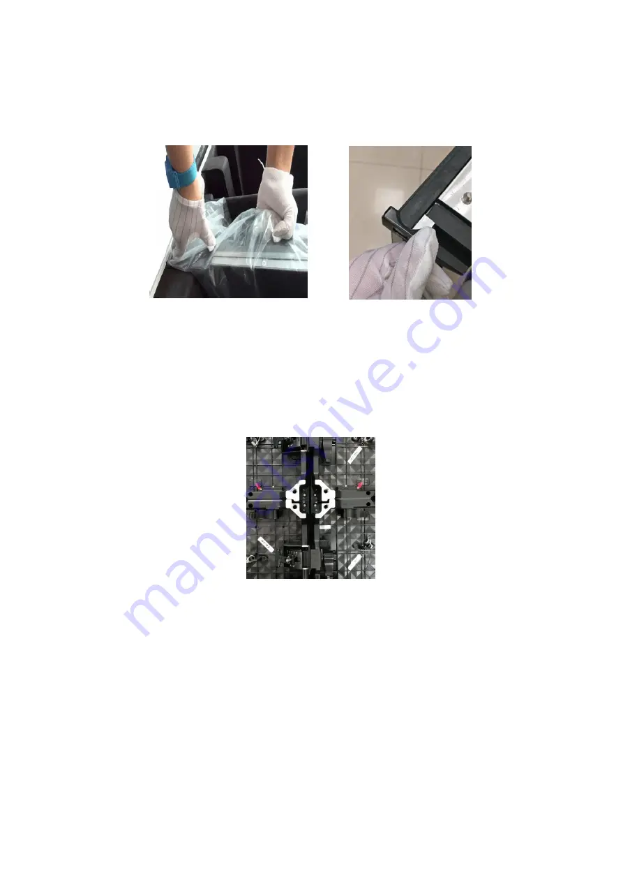
the automatic corner guard, the side of the sheet metal corner needs to be removed
with a screwdriver to remove the corner guard.] Place it on the ground or on the table,
as shown in Pictures 6-14, 6-15.
Picture 6-14 Take out Cabinet
Picture 6-15
Press to protect the
automatic corner
3. Start installing the cabinet. After ensuring that the truss and flykits are flat, gently
place and lock each cabinet. Each time a cabinet is erected, a cabinet is lit
immediately to check if any dead lights and obvious bright lines. Plug in the power
cable and signal cable into socket of the cabinet, a “crispy” sound after plugging
indicates good connection.
Picture 6-16 Lock the cabinets
4. Repeat step 3
,
Until the entire screen is installed. Refer to Chapters 7 and 8 for the steps to debug
the display.
6.2.3 Precautions:
1. During the installation process, pay attention to the protection of the cabinet to
prevent the cabinet surface from being bumped and the cabinet from tipping over.
2. The maximum number of hanging cabinets 16.
3. Before installing each cabinet, you need to connect the power cord and conduct
pre-testing to ensure that there is no abnormality before installing.
Содержание VMR-O P3.9
Страница 1: ...1 66 Product Manual VMR O P3 9 ...
Страница 34: ...34 66 Appendix A Dimensional Drawing of Main Components A 1 VMR O VMR O P3 9 Flat Panel Curve Panel A 2 Flykit ...
Страница 41: ...41 66 C 5 Plastic hammer ...
Страница 49: ...49 66 ...
Страница 53: ...53 66 F8 Press the lock handle according to the mark to lock the cabinet as shown below ...
Страница 55: ...55 66 G4 Open the back cover of the power supply cabinet as shown below as shown below ...


