76
Save button in the Enable/Disable Calibration panel
Click this button to save the calibration switch status (enable or disable) to the
hardware.
Save button in the communication log panel
Click this button to save the communication log to a text
file.
Manage Coefficients
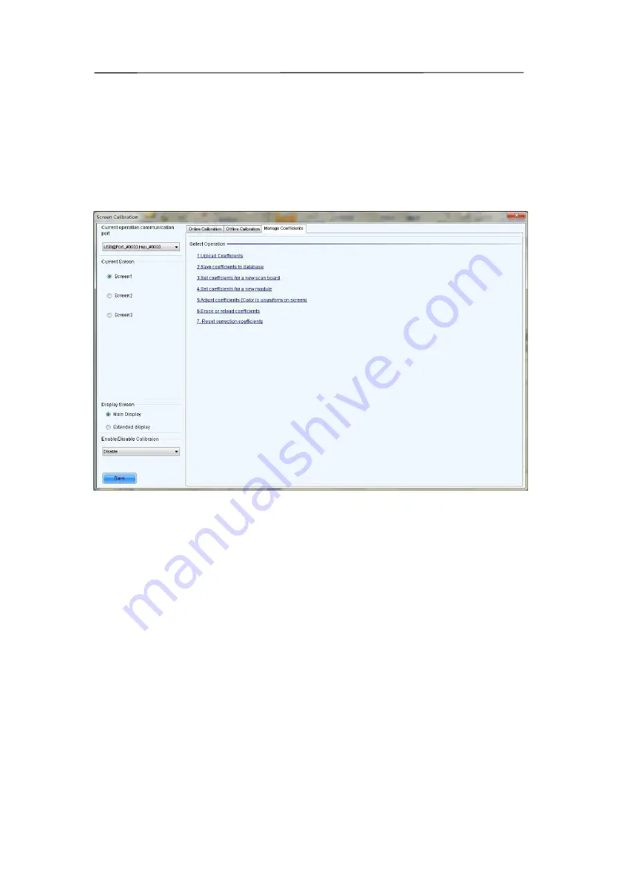
This page is to adjust the calibration coefficients for better calibration performance. Shown
in Fig.9-14is the Manage Coefficients page.
Fig 9-14
Upload Coefficients
Upload a calibration coefficients database to the LED display.
Save coefficients to database
This operation is to read back the calibration coefficients form the LED display and save
them to a database file.
Set coefficients for a new scan board
This option is to set the calibration coefficients for a newly placed receiver card in the LED
display.
Set coefficients for a new module
This option is to set the calibration coefficients for a newly placed module in the LED display.
Adjust Coefficients
This option is to adjust the calibration coefficients of the selected LED display area for better
performance.
Erase or reload Coefficients
This option is to erase or reload the calibration coefficients of the selected LED display.
Содержание P10
Страница 3: ...3 10 1 Cleaning 104 10 2 Calibration 105 10 3 Replacement steps 106 11 Appendix 119 ...
Страница 12: ...12 3 2 Product Appearance ...
Страница 13: ...13 ...
Страница 14: ...14 3 3 Product design Decomposition chart ...
Страница 15: ...15 Assembly drawing ...
Страница 16: ...16 3 4 Product main components Module Power Supply Receiving Card Monitoring Card ...
Страница 17: ...17 Fan Hub board Power data cables 16pcs DC power cables 8PCS and Flat cables 16 pcs ...
Страница 35: ...35 Installation of cabinets Fixing of connect plate ...
Страница 41: ...41 8 Connection of the LED screen 8 1 Connection for equipments Connection between Sending box and PC ...
Страница 42: ...42 8 2 Port of Cabinet and serial number paint ...
Страница 59: ...59 ...
Страница 68: ...68 ...
Страница 79: ...79 Click Next to open the page for Step 3 ...


