Troubleshooting
Samsung Electronics
4-53
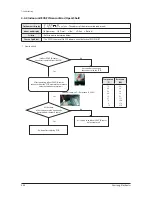
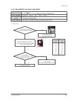
4-4-9 Electronic Expansion Valve opening malfunction (2nd stage) -
1. How to diagnose
- During Cooling operation, the temperature of the inlet or outlet of stopped Heat Exchanger is kept lower than 0˚C for more than
20 minutes without cessation.
- Hydro Unit : During the defrost operation, detection from stop-side Indoor Unit. (Temperature of the inlet of Heat Exchanger is
kept lower than 0˚C for more than 20 minutes without cessation.)
2. How to check
* How to turn off the Hydro Unit E151
- Hydro Unit PCB k1, k2 switch : At the same time push for more than 4 seconds.
- After resolving the cause of the error, restart operation.
(Excessive reset operation, can cause damage to the Heat Exchanger.)
전자
팽창밸브
정상
작동
Is the EEV wire connected to the PCB?
Yes
No
No
No
No
Yes
Yes
Yes
Connect to PCB and restart operation.
Connect the EEV coil properly and
restart operation.
Is the EEV coil connected to the main body properly?
After measuring
the coil terminal resistance, is there a disconnection or
short circuit inside the coil?
Normal operation of EEV.
After Resetting
the Outdoor Unit, does an error occur even after
running it again with the same
combination?
Replace EEV coil
Outdoor unit display
1st detection : P703 (Outdoor Unit display only)
2nd detection :
x x x (x x x : The address of the error occurred indoor unit)
Indoor unit display
×(Operation) ×(Timer)
◑
(Fan) ×(Filter) ×(Defrost)
Criteria
• Refer to the judgment method below.
Cause of problem
• Faulty Indoor Unit EEV action. (Refrigerant will leak into the stopped Indoor Unit.)
Содержание AM032MNQDCH/AA
Страница 343: ...PCB Diagram and Parts List Samsung Electronics 5 13 Duct type HSP Small MA 2 Drain Pump Built in cont BLDC PCB 2 3 4 1...
Страница 345: ...PCB Diagram and Parts List Samsung Electronics 5 15 Duct type BIG Duct cont EMI PCB 1 2 3 5 4...
Страница 347: ...PCB Diagram and Parts List Samsung Electronics 5 17 5 1 6 Celing type 1 2 3 4 5 6 7 19 18 9 10 11 12 17 15 14 13 8...
Страница 364: ...PCB Diagram and Parts List 5 34 Samsung Electronics OAP DUCT AM6JNESCH AA cont BLDC Driver PCB 6 5 4 3 2 1...
Страница 378: ...PCB Diagram and Parts List 5 48 Samsung Electronics 5 1 16 360 cassette MAIN PCB 1 2 3 4 5 6 7 8 9 10 11 12 13...
Страница 384: ...Wiring Diagram Samsung Electronics 6 3 6 1 3 BIG Duct This Document can not be used without Samsung s authorization...
Страница 385: ...Wiring Diagram 6 4 Samsung Electronics 6 1 4 Ceiling This Document can not be used without Samsung s authorization...
Страница 387: ...Wiring Diagram 6 6 Samsung Electronics 6 1 6 RAC Neo Forte This Document can not be used without Samsung s authorization...
Страница 393: ...6 12 Samsung Electronics 6 1 12 OAP Duct type This Document can not be used without Samsung s authorization...
Страница 394: ...Samsung Electronics 6 13 6 1 13 Wall Mounted type Boracay This Document can not be used without Samsung s authorization...


