EB 7500 EN
13
Start-up and settings
< >
Increasing/decreasing:
Position
(x-w) </= 0
> >
Increasing/increasing:
Position
(x-w) >/= 0
Setting the control error
The setting depends on the system and must
be determined by experimenting.
Starting with a high value, perform the set-
ting in steps with an increasingly smaller
control error.
To ensure that the switchover point for P and
PI or PD and PID control mode is not continu-
ously exceeded, set the control error (x–w),
keeping the error deviations that occur in the
system due to constant disturbances within
the adjusted (x–w) range.
It is often recommendable to set the control
error (x–w) to be double the Kp value set at
the controller module.
Setting the operating point
When the system is in a steady-state condi-
tion, move the operating point adjuster to the
value of the manual output yA (reading at
the manual control station) (0 to 100 % cor-
respond to an output of 0.2 to 1 bar).
In case of large and frequently changing ref-
erence variables, we recommend setting it to
50 %.
Set-point-dependent operating point
In this version, the operating point is auto-
matically tracked, meaning that the system
deviation remains at zero. The set point ad-
juster allows, however, a proportional shift
of ±20 %.
Feedback limitation
The additional feedback limitation allows the
output pressure yA to be limited. In this case,
the 0 to 100 % scale of the adjuster corre-
sponds to a limitation signal of 0.2 to 1 bar.
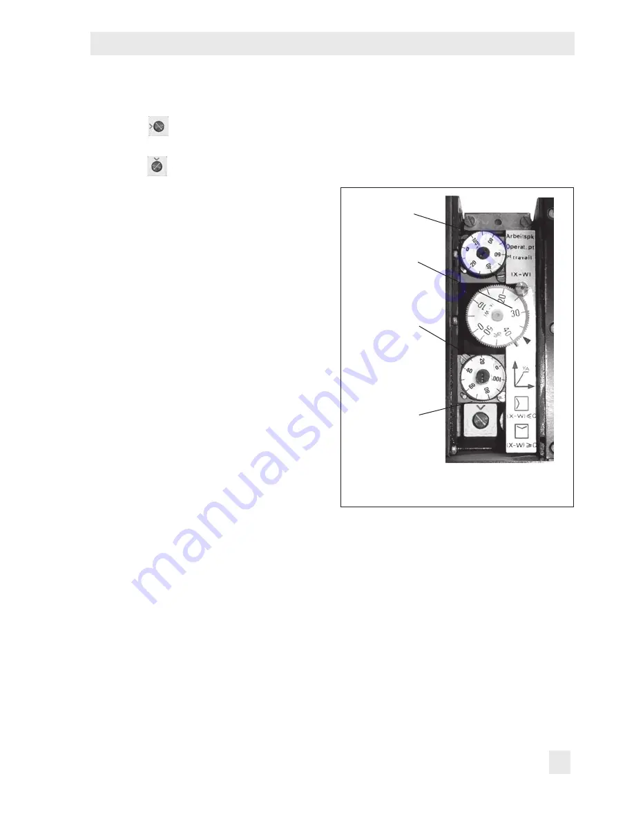
Fig. 5:
Type 3424-5 Control Mode
Changeover
4.4.3
Type 3424-6 Signal
Limiter
Use the corresponding adjusters to perform
the minimum or maximum signal limitation
(Fig. 13). In this case, the 0 to 100 % scale
of the adjuster corresponds to a limitation
signal of 0.2 to 1 bar. See
u
T 7523.
Operating point
System
deviation
y
A
limiter
Direction of
action of
turnboard
Содержание Series 420
Страница 37: ...EB 7500 EN 37 ...
Страница 38: ...38 EB 7500 EN ...
Страница 39: ...EB 7500 EN 39 ...


